#0037: Tip for securing a cabled USB type-A plug and socket together
Preamble
This is a quick budget tip for securing a cabled USB type-A male and female plug and socket together. This technique could probably be extrapolated for use with other plug types. However I have yet to do so.
Tip for securing a USB type-A male and female plug and socket together
Now onto the tip. Simply put, I use an elastic band to hook the two plugs together. That’s it. Done. Thank you for reading…
Still here? Okay, now onto the part where we explore in excessive detail such a simple concept. One so simple you probably have immediately intuited the basic theory of operation. If not then here it is. Basically, the elastic band applies a pulling pressure that keeps the plug and socket engaged. This is especially useful when you have an otherwise loose connection, typically caused by issues such as weak retention springs within the female socket. Something that seems common to USB extension cables in my opinion. At least the ones I have encountered.
Method of application
I like to start by using a basic cow hitch to lasso one of the plugs. This is done by folding the band into a loop and simply inserting a plug into this loop. Then tightening it around the plug’s plastic shoulders. That’s a basic cow hitch.
Now, with the other side of the elastic band wind it around the plastic shoulders of the second plug a couple of times until the elastic is reasonably taught. Then insert the male into the female plug. And done. The band should now exert force that will keep pulling them together.
Elastic band application demonstration video
Best practices
For best results, I recommend using a reasonably strong elastic band. I also recommend only wrapping it around the plug’s plastic enclosure itself, and not involving their respective cables. This is so that no force is applied to the cables themselves. Force which may aid in the development of faults such as repetitive flex damage, or a kink in the cable. Additionally when the band is secured on the plug body it focuses and directionalises the force in a way that better pulls the cable ends together.
An attentive reader may notice that in one of my example images, the one with the beige elastic. The upper band loop is a little bit too high up, and sits on the plastic wire strain relief itself, rather than the plastic plug body. What can I say? Do as I say, not as I do. 😉 Its really not a huge deal either way. Securing the loop on the plug body is just what I consider best practice.
Why not use adhesive tape instead?
Alternatively to using elastic bands, you may think: why not use tape to adhere the two ends together? Briefly put, tape is messy – it leaves glue residue when removed, it’s too permanent or hard to remove, and probably most importantly: it doesn’t put pressure on the plugs to keep them together. So as time passes the plug could slowly but steadily slip out of it’s respective socket. Due to things like vibration, gravity, or general handling.
Closing thoughts and my use-case summary
In my particular use-case, I use elastic bands like these to keep the USB extension cables attached to my 4 Watt USB lights and their switches. The weak retention springs within the female USB sockets on the extension cables allow any plugs inserted into them to eventually slip out.
I used to use electrical tape to manage this but, as time went on the tape lost it’s adherence. Yet left a mess of melted glue residue. After this I switched to using duct tape, but it was too strong, and too difficult to easily remove when I wanted to. Hence the bands. Third time the charm it seems.
So far, just common garden variety elastic bands seem to work best for me in this application. Whatever you can find is fine. Funny thing is, I didn’t even buy them. I just collected the ones that my mail man keeps dropping around my door.
All in all. This is an example of a zero budget application of junk that has gained value via use. At least I found it to be so. Anyway, I hope this article is of use to you. At the very least I hope I can raise a little awareness of the genuine potential uses of random household miscellanea. And that it may assist you in exploring alternative DIY solutions to purchasing one’s way out of any given problem. I know I have been guilty of that.
#0035: repair and analysis of a talon style folding lock knife
Preamble
I was recently given this folding lock knife to fix for someone. The internal mechanisms of which I found mildly interesting, so I figured it would be worth the time to document it. It may also prove useful for future reference incase I come across something similar.
Initial observations
The first thing that I noticed whilst examining this unit is the unusual blade shape. This is a talon type blade. It is a single edged, crescent shaped blade that curves forwards and terminates in a single point. It’s crescent shape, coupled with the blade edge being on the inner concave curve: give it both a visual as well as function resemblance to the talons of birds of prey. The blade is designed to roughly function in the same way: to pierce and then to hook. This shape of blade can easily convert slashing motions into pierces, due to the blade tip being the leading contact point.
The blade description above may lead you to think that the pictured example knife is a deadly weapon. And that would be the case, at least if not for my second immediate observation. Which is that this knife is a mass produced (I assume) chinese special tacticool toy knife.
It is rather cheaply made, and only really aesthetically resembles the weapon that it is aping. This pictured knife is just a box cutter. That is also it’s literal function currently. Its what the knife’s owner, who is a warehouse operative uses it for. It is also the only thing that it can be used for in my opinion.
Faults
The main thing that was wrong with this unit is that it was not maintained properly. The owner did not tighten the various torx screws on this thing as they worked themselves loose. This led to various joints and mechanisms developing too much play in them. This then resulted in the blade being seated at a crooked angle. Which in turn allowed the blade tip to scratch the handle as it was retracted into it.
Additionally due to the owner’s negligence: some of the various screws that loosened over time, fell out entirely and were consequently lost. This is rather unfortunate, because these fittings consisted of a paired torx screw and socket nut; that where sized to fit flush into the recesses of the handle plates. The socket nut especially is rather annoying to replace. Requiring a specific purchase as it is rather uncommon, and wouldn’t likely be present in any of my bins of miscellaneous salvaged hardware.
The blade itself also has an issue. The main one being that it is made from a miscellaneous soft junk metal; and the second one is that it was currently dull. So it required a basic sharpening, in order to make this knife operable. At least for the relatively short time period that the blade’s soft metal can maintain a serviceable edge.
Parts list
A complete version of this locking knife consists of several discrete components:
1 x camouflage painted outer metal knife handle plate (left)
1 x camouflage painted outer metal knife handle plate (right)
1 x black painted metal inner frame with spring compartment insert gap
1 x black painted metal inner frame with blade locking wedge
1 x black painted metal finger guard with box cutter point
1 x grey painted talon style blade
1 x metal spring
1 x metal spring compartment
2 x plastic washers
4 x smaller black painted metal hex screw and blind nut set
1 x larger black painted metal hex screw and blind nut set
1 x black painted metal trouser clip
3 x black painted hex screws for the trouser clip
Tools and materials
Tools:
Round edge metal file
Knife sharpener rod
Torx screwdrivers (T7, T9)
Tweezers
Materials:
plumber’s grease (or equivalent)
Repair
There really isn’t much to say on the repair itself, as its pretty straight forward. I disassembled then reassembled the knife; fixing everything dodgy about it as I went.
Actions:
Completed knife disassembly.
Bent the blade locking wedge on the inner frame so that it stops the blade from folding closed more reliably.
Greased the blade’s damaged plastic washers to help prevent future wear.
Bent the blade spring’s hook into a right angle in order to get a better hold on the blade.
Re-greased the blade spring within the spring compartment due to presence of dry grease here.
Re-tightened all the screws and socket nuts that keep the housing together.
Added a stand-in replacement for a missing screw and socket nut pair that consists of two screws and a salvaged threaded brass insert nut.
Added a plastic screw and nut to help hold frame. I chose plastic so that I could cut down the screw and round off the nut easily so that it doesn’t snag the user’s hand.
Performed a basic sharpening on the blade using a metal file, then honed the edge using a knife sharpening rod.
The actual repair itself is hardly anything to be proud of. It wasn’t a hard repair and didn’t even take long. However this knife has been saved from going into the rubbish bin, for at least another couple of months, and that should be the main take home. This thing is ready for work again; and should stay that way for quite a while.
Before and After video demo
Before
After
Recommended modifications
1) Grinding the blade edge and sharpening.
The knife blade could use a proper grinding and sharpening: if it to be used for anything more involved than opening boxes. I recommend grinding the blade down so that the angle of the blade edge slopes smoothly up to the mid-ridge. That way the blade can have more acutely angled edge.
This will consequently make the blade sharper than it currently is. A smaller angle will also remain sharper for longer whilst in use, due to the relative thinness of the new blade edge. Even as it dulls. Although the blade will also likely become more brittle and likely to snap as a consequence of the severe loss of material this newly angled edge will require.
2) Installing a blade backstop.
A blade backstop will stop the blade from over-rotating when it is extended. It will also prevent the blade from wobbling when extended by sandwiching it between the backstop and the blade locking wedge.
This knife likely already had a blade backstop of sorts, as it already has the screw holes where on could be mounted. However it was probably lost during use. As it is the blade overextends backwards when it comes in contact with any material that resists it.
3) Thread locker on the screws.
Thread locker such as “Locktite 243” when applied to screws prevents them from slowly working themselves loose during operation, due to factors such as vibration. This will extend the lifespan of this knife when applied to the screws that hold the frames together, as it will mean that they will (largely) no longer need to be checked and re-tightened at intervals.
And since we have already established that this knife’s owner is averse to maintaining his equipment: the lower the level of maintenance this knife needs, will be proportional to the extension of it’s operational lifespan. I.e. it will last as long as it lasts, if the thread locker can keep it together for longer, than it will last a little longer as a consequence.
4) Installation of additional retaining bolts.
I think that installing a few additional bolts and nuts to keep the frame together would greatly increase the overall structural strength of this folding knife. As it would share the strain of keeping the unit together amongst more points. This would allow this knife to be used in applications that require more force.
Although one has to be careful not to drill and install any bolts within the blades seating area within the knife handle housing, or within it’s pathway. Common sense right?
Post mod roles
As it is this knife tool is weak and too dull for any real work beyond cutting the tape off of cardboard boxes. however I theorise that if the above mods are made, then one would end up with a stronger, sharper, and more stable tool.
This would then allow the tool to used in a broader array of applications. For example light wood working, or bush craft applications. A talon style blade is good in both of those applications. The sharp hooked point is good for carving detail into wood. The concave blade is good for gripping and working with rounded objects like natural woods (sticks and branches). For example: for sharpening sticks, or for feathering wood to create tinder. It is also good for harvesting (in this case smaller) plants; as the concave blade helps bundle the stems together when cutting. Like a miniature sickle.
I could go on but I hope you get the point. The issue here is not with the knife’s design, it is with it’s flawed construction. If that could be remedied (or at least alleviated), then this knife could actually become a useful tool. It just requires work to get there.
Closing thoughts
Honestly, I actually rather dislike these types of low-cost low-quality mass produced items. This knife for example: it’s low-cost promotes replacement rather than repair: as it can very quickly make many repairs in it’s owner’s eye deemed as uneconomical. And that is assuming that the owner has a mend-and-make-do mentality to begin with. Most contemporary consumers do not. They have a use and replace mentality.
The main reason why a person may want to repair these things in my mind: is either philosophical (i.e. environmental conscientiousness, fiscal responsibility, anti-consumerist sentiments, etcetera); emotional sentimentality (e.g. hand-me-down from a relative); or if they are in severe financial strife and literally can’t afford to replace a £3.99 work knife.
Now look at it’s cheap build and materials. This factor exacerbates the issue above. Chiefly because it lowers the tools operational lifespan. This is the time it is in use, before it somehow breaks on it’s owner. Hence sooner putting them in a position to make the call on whether or not to either repair or replace the tool.
I do consider a knife like this to have been built with planned obsolescence in mind. Even though the term is hardly used for mechanical hand tools like knives; as it is usually reserved for electronic or computer products.
However, consider this: if the user does no maintenance on this knife. Then there are only so many operational hours that it is capable of before completely falling apart, or at the very least becoming inoperable. It’s shoddy build quality purposefully limits this simple hand tools lifespan. And when it is over, the user is expected to then purchase another one. That is a form of planned obsolescence.
I hate preaching, but please consider not buying this kind of shite. There are better alternatives available. Such as buying second hand quality tools. I always advise that people do the requisite research first. Then spend what they can afford in order to get the best value tools that they can, for their specific use case.
I said “Best value”, not most expensive. A chrome-vanadium spanner is a chrome-vanadium spanner at any price. Just because a person pays more for a brand name, doesn’t necessarily mean that their chrome-vanadium spanner is better than the off brand one.
Nowadays, it’s rather likely that they were both made in the same factory from the same material stock. An idea that would be laughable, if it wasn’t also true. Many brands on the market don’t manufacture anything. They purchase orders from the same OEMs then label the products as their own.
*proceeds to mount high horse.
If you absolutely have to purchase at the bottom of the market because you absolutely have no more money to spend. Then spend time instead. Time upgrading, fortifying, and maintaining your tool. This is so that it can last as long as you need it to. Or at the very least extend the time intervals between new purchases.
That being said, it is an unfortunate reality that most people who do mindlessly purchase bottom of the market products like this knife: are either unable; or more commonly, unwilling to invest time in their tools. They are in many cases content to use the shoddy tool in the short time until it breaks. Then purchase another bottom of the market shoddy tool to replace it with. Repeating this loop of short-sighted wasteful false-economy ad infinitum.
*proceeds to dismount high horse.
I feel that I should somewhat qualify my rather negative sentiments against these types of bottom market products. In the past I have worked within a small recycling facility, one that primarily serviced my local community on behalf of the local council, as well as the surrounding areas. (The point is that we weren’t shipping it’s garbage in.) I worked there as a materials sorter.
It gave me a certain perspective on the sheer volume of material wastage people engaged in. For a supposedly poor community, the amount of waste of useful materials was astounding. Every night I came across hundreds (not hyperbole) of very useable tools of all kinds. Everything from: screwdrivers, knives, drill bits, and spanners, to pots, pans, skillets, as well as whole bicycles some nights. All of that thrown away for recycling.
Many of these things were in decent conditions. Conditions that required either basic maintenance such as: sharpening, some hammering, replacing a handle, or realigning, or even a simple old fashioned cleaning. Gasp! Working there made me dislike a lot of these products; as when I now see them new: I think of where they’ll likely end up in less than a years time … In the fucking trash.
I just don’t like companies purposefully making tools/products that have such a short lifespan designed into them. I doubly don’t like it when these same products are purchased, used, and then wastefully discarded, by people whom I have heard a thousand times: claim poverty. But that’s another rant entirely.
I recently had to repair a constantly dripping kitchen faucet, and thought that I may as well document it. Especially since I found the construction of the cartridges within the tap to be rather interesting. Although I must say that the title does make me feel a bit silly.
Tools and Materials used
Tools:
crescent wrench / 17mm wrench
nylon spudger / pry tool
phillips screwdriver
soft bristle toothbrush
plastic container
pipette
teaspoon
Materials:
petroleum jelly / plumber’s grease
vinegar
water
Tap cartridge inspection
I’d like to start by examining the water faucet’s cartridges themselves, as this information will be relevant later during the repair. The two pictured cartridges were taken from a quarter turn kitchen tap. This is a tap that only requires the handle to be turned 90 degrees around it’s axis, in order for it to go from a fully shut to a fully open state, and vice versa.
This type of cartridge is designed so that water flows into it from the central hole at it’s bottom inlet. This water then flows up inside it’s shaft, and through the two holes within the first ceramic disc. It is then diverted out through the two radial holes on it’s side via the second ceramic disc. At which point the water has a direct route to the faucet head.
This particular type of cartridge has two ceramic/plastic discs within it, that in conjunction with each other operate as a single water control valve. They do this by establishing a water tight seal between them; a press fit seal that is created by the two discs merely pressing against each other in a way that eliminates any gaps between them.
This seal is demonstrated within the video below, where you can see a suction effect take place between the two discs. This suction helps the two discs adhere to each other when wet. This is only possible due to the absolutely smooth surface of the first disc, coupled with the hollow cups present on the second disc’s contacting surface.
These two ceramic valve discs are both keyed to fit into their brass metal shaft in one particular orientation. This orientation has the bottom disc operate as a fixed or stationary valve. Whose job it is to split the ingressing water into two separate streams. It does this via the two distinct triangular quarter-circle holes within it. This lower disc is keyed to fit into the inner wall of the cartridge’s cylindrical housing in a way that makes it immovable.
Whereas the top disc is keyed into the rotating tap handle cylinder attachment. This allows the tap handle to control the rotation of the upper disc. This upper disc is cut in a way that either blocks the two water channels provided by the bottom disc when closed; or when open: diverts water from the holes of the bottom disc outwards to the radial holes in the cartridge housing. This water is then further diverted up and out of the tap for use.
The reason why it only takes a quarter turn to fully open the water channels of this type of cartridge: is due to the placement of holes and channels within these ceramic discs. The first (bottom) disc has two oppositely placed holes within it. Each taking up approximately a quarter section of the circular valve.
This quartering is then reflected within the top ceramic disc. Which consists of two opposing cupped flat plates, and two opposing angled wedges: which veer off to the radial holes within the brass cartridge housing. And since these channels take up opposing quarters of their discs – it only takes a quarter turn to either align both holes of the bottom plate with the upper disc’s water outlet ramps, which then allows water to pass; or with the flat plates, which then blocks the water at both holes.
Cartridge operation demo video
Valve operation demo video
Suction effect demo video
Dripping fault Analysis
Dripping fault cause theory
The fault that causes a dripping tap can be due to a number of different factors. Probably the most straight forward scenario includes water simply making it’s way around the rubber o-rings and/or water gasket. This could happen if the rubbers have gotten old or heat damaged, and started contracting or cracking as a result. Alternatively, they could’ve been disturbed or are otherwise not seated correctly in order to form an effective water barrier.
This means that whatever water does manage to get around these seals can then bypass the cartridge altogether and shortcut it’s way to the faucet head. The severity of the leak in this case would be directly proportionate to the ineffectiveness of the rubbers to seal out water.
Another issue could be within the cartridge itself. With water entering the cartridge and then passing through the cartridge valve by squeezing between the two ceramic disc plates due to an imperfect seal. This pressure fit seal between the two disc plates could be undermined by a number of different factors.
The most likely of which are a build up of limescale on the the ceramic discs themselves. Limescale is a broad term to encompass residual build up of the carbonates present in drinking water; such as calcium and magnesium carbonate. Water rich in minerals like this is often referred to as “hard water”.
Limescale build up on the contact surfaces between the ceramic discs, can cause them to then become uneven as the limescale adheres to them. Specifically the drip issue is caused because the valleys in this now uneven surface provide the water a small pathway across the pressure seal’s threshold when it is closed.
Another issue that could cause the valve to no longer function effectively is scoring of the inter-disc surface. Essentially scratches that then allow some water to pass through their valleys when the valve is closed. A likely cause of this could be something as basic as wear and tear. The two discs grinding each other down over an extended period period of time due to standard use. This happening with just the minor friction created from repeated opening and closing over time, eventually compromising the watertight seal as disc surface material is lost.
Before moving on, I should mention that this section is largely speculation. Basically educated guesses based on my observations during the disassembly. That being said these theories above are the one’s that I went into this repair with.
Dripping fault effect
A continuous drip may initially seem like a minor fault, because it is. However, this fault incurs a waste of resources. A slow but continuous one, that is hard to easily assess. Simply put it wastes water, and probably more than you might expect as well. Just because it only wastes a drop at a time, it doesn’t mean that it isn’t wasting a lot cumulatively. It just makes it difficult to easily see the totality of wastage.
Sampling methodology
Let’s try to get a rough idea of how much water is lost due to this fault. Note that this is not going to be very scientific. It is just a test to get a rough idea of water wastage. With that in mind, there are two discrete pieces of information that are required: 1) is the average water droplet volume; and 2) the number of water drips within a set period of time. In this case the sample time will be 1 minute.
I captured a single drop using a teaspoon. Then sampled it using a random plastic pipette that I had on hand. I repeated this a few times and found the droplets to be rather consistent in volume. Unfortunately, due to the pipette’s lack of precision, I was forced to visually estimate this volume between it’s labelled increments.
Collected observations
This leaky tap consistently provided around 13 drips within any one minute period.
With each drop having a volume of approximately 0.3 ml each.
Water drip rate and predictive volume lost
1 minute: 13 drips @ 3.9 ml
1 hour: 780 drips @ 234 ml
1 day: 18720 drips @ 5616 ml (~5.6 litres)
1 week: 131040 drips @ 39312 ml (~39 litres)
1 month: 524160 drips @ 157248 ml (~157 litres)
Leaking faucet demo videos
Droplet sampling demo video
Leak conclusion
Interesting result. If a household either has a limited water supply (e.g. off-grid), or is on a metered supply where they pay for water by volume; then 157 litres lost in wastage in a single month by a single tap is not insignificant.
I hope this has illustrated how important it is to fix even minor faults such as this as soon as possible. 157 litres of water used could very well cost a metered household more money on the fault’s first month on the household’s monthly water consumption bill, than a complete cartridge replacement for that tap otherwise would have.
Repair process
Getting at the parts
First thing first. Common sense. I switched off the water by closing the main water valve for the house. This was located under the kitchen sink for me. This is an essential step in the same way as one would switch off the electricity before working on an electrical outlet, one needs to turn off the water before working on a water outlet. You’d think that was common sense right? But I have seen too many plumber fail videos online that say otherwise.
After giving the kitchen faucet a once over, and looking online I decided that the tap cartridges are the most likely suspects for the drip, so I set upon getting at them. Since I have never taken a kitchen sink tap apart before, I engaged in what I call an exploratory disassembly. Prodding and poking the device looking for hidden clips and screws.
To cut to the point: I used a nylon spudger to pry open the (metal coloured) plastic screw cover on each tap. I recommend using a plastic pry tool to avoid scratching the finish off of any part of the tap. Next. I unscrewed the phillips metal screws which attached each tap handle to the rotatable cartridge cylinder section below them. After setting aside the tap handles, I then removed the full cartridge assembly from the faucet housing using a wrench. As for disassembling the cartridges themselves, they come apart toolessly in-hand. That’s it. Easy.
Inspection
Like every repair, this one begun with a thorough inspection. A basic visual inspection did not reveal anything obviously wrong with either cartridge to my eyes. However once I disassembled both hot and cold units, I noticed that the internal plastic disc valves on the cold water side felt rough to the touch. Likely indicating a build up of limescale. Most notably this was even apparent on the surfaces between the two valves. And since these two surfaces come together to form the press fit seal that controls water flow: I concluded that this was likely the specific cause to this particular leak.
Limescale build up is nothing unusual for my particular location, as I do live in a heavy water area. However the odd part was that all the limescale build up was on the cold water side cartridge of our kitchen tap. With little to none on the hot water cartridge. This is really unusual in my opinion because I believe that higher temperatures should exacerbate limescale build up. The average water kettle should be a testament to this theory. However in this case the limescale build up was only sufficiently present on the cold water side.
A working theory I have concerns the on demand water heater which directly supplies this tap – a boiler which my household recently (1.5 years) had professionally installed. I believe that it has some-kind of water filter (or softener, or descaler…) that has been fitted to minimize limescale build up within the unit as it heats water. This means that the hot water provided by it to the tap would have less mineral contaminants (i.e. be softer) than the cold side. I would verify this, but it is not a pressing issue and not worth digging the unit out at this moment to confirm.
Cleaning the cartridge
Once I decided that it was limescale that was undermining the valves press-fit seal, I decided to take the already disassembled cartridges and submerged them into a vinegar solution. The idea is that the mild acid of vinegar will react with the alkaline limescale and dissolve it into the liquid solution.
After about an hour, I removed the parts and brushed them all down with a basic toothbrush in order to remove any loosened remaining debris. I did however take care not to scratch or score the plastic valves as any scoring would also undermine their ability to form a watertight seal; as this would allow water would pass through the miniscule divots that would be present on the seal’s contacting surfaces.
With regards to this method, I should note that I made exceptions for the rubber parts of the cartridges. The blue o-rings and red/blue rubber gasket. I just did not feel comfortable submerging them in an acidic solution for extended periods. I feared that it may affect the chemistry of the rubber material and ‘dry’ it out. Thus causing it to crack or split; and consequently be no longer effective as a waterproof seal. (FYI the pictures below are lying.)
Testing
After a quick rinse in tap water I decided to reassemble the cartridges and put them back into service for extended testing. Although the leaking was significantly reduced as it didn’t drip continuously as before: it still dripped regularly. This was tested by leaving an empty cup under the tap head overnight. I’d regularly find the typical coffee cup I used at least half-full come morning.
This lead me to surmise a number of scenarios:
1) That the water was making it in between the the plastic valve seals. Likely due to surface scoring caused by either my cleaning/brushing of the valve discs; or the limescale itself being ground into the discs as they operated over the years.
2) Water is making it’s way around the gaskets and o-rings, in addition to bypassing the valves. And that I have only remedied/alleviated one issue.
Greasing the cartridge components
With these conclusions I decided to then purchase some plumber’s grease. Thinking that it would be perfect for the application of assisting the plastic disc valves and rubber gaskets to form water tight seals. The Ebay listing for it explicitly stated just that.
However once the product arrived, I decided that I wouldn’t be testing it’s efficacy as I decided that it was not fit for use. The reason why: was that the little tin came with a whole host of warnings on it’s label. Warnings typically associated with poisonous chemical products.
Particularly the “Do not eat, drink, or smoke …” around this product warning gave me pause. Especially when coupled with the fact that the very vapours from this thing were an irritant. It emitted a vapour that was a mild irritant to the eyes and nose, smelling almost minty like the ointment “tiger balm”.
So despite the labelling assuring me that it is indeed appropriate for use within water faucets, I decided that this was not something that I wanted coming in contact with my drinking water – and ultimately ending up inside me. Maybe I am just paranoid. Maybe not.
Either way if an irritant chemical has warnings not to ingest it, and by using it for it’s intended purpose you are essentially guaranteeing ingestion. Maybe don’t use that chemical. Ultimately, it all just comes down to personal choice, and how much you trust anonymous Ebay sellers over your own intuition.
Personally I just found a substitute: Petroleum Jelly. A non irritant, non toxic chemical that routinely comes in contact with human skin and lips. So chances are good that it won’t do any harm if you accidentally ingest some with your drinking water.
Additionally unlike the plumber’s grease, the jelly can be used with rubbers like the o-rings and gaskets. I used to use some back in school within the science lab. A small amount was applied to the mouth of a bunsen burner’s rubber gas hose in order to help form a gas-tight seal between it and it’s brass attachment. I remember it even hydrating the dry red rubber of those hoses. Although I am pretty sure that petroleum jelly is also flammable so I’m not sure if that was a particularly safe application for it. :/
However within this application: my only concern with petroleum jelly is it’s longevity in the system, and heat resistance. However those are considerably less concerning than putting poison in a drinking tap. So after greasing everything up: the o-rings, the rubber gasket, and the plastic valve discs, then tighten everything down properly – I did note further improvement. Now the faucet barely leaks at all. Barely being the keyword here.
Jobs a gudd’un mate.
Post repair review
I left some time after the repair for observation before writing this review and it seems the leak is slowly returning after a month. A month of constant use keep in mind. I am still chalking it up as a success because this repair really only needed some basic tools and materials. The only consumables used are just household sundries like vinegar and pure petroleum jelly. So it can be done for next to nothing.
There are even more things I could do short of purchasing replacement cartridges, and that would be to use an additional o-ring under the main water ingress rubber gasket. This will put more pressure on the plastic disc valves. Squashing them together to form an even tighter pressure fit seal between them.
Although there are likely drawbacks to this, including and not limited to: firstly, a stiffer tap – the more downward pressure on the cartridge mechanism, the harder it would be to rotate it; and secondly, the higher pressure on the discs themselves would cause them to grind against each other more, and likely shorten their lifespan by promoting scraping of their contact surfaces.
Although if you are repairing it in the first place, chances are that they are already well towards their end-of-life, in which case this fix will extend it couple of months before they likely fail into a unrepairable state. At which point replacing the ceramic discs will be needed. Just my guess.
Closing thoughts
Not much to say here really, I surmised my thoughts on the repair itself within the Post repair review above. So I’ll go with a more personal note here.
I actually enjoyed looking at this tap cartridge more than I thought I would. It really is amazing what people are capable of creating through iterative design and mass production. It reminds me of the gaming concept of min-maxing: of getting the most out of the lest.
I mean look at the simple design and construction of this cartridge. It uses two plastic/ceramic discs to create a watertight seal by just pressing against each other. Undoubtedly the results of iterative cost cutting to the point of being adequate or acceptable, and little more.
I know that when I usually talk about cost cutting, especially when discussing mass produced goods: its usually in a negative light. That’s because the stimuli or catalyst for those tangential rants tends to be a product that is sub par, and in my opinion not fit for purpose. Products that I refer to as “factory fresh e-waste”.
However that is not the case here, these cartridges are fit for purpose. But they are also (in my humble opinion) built down to a price point. One that makes economical sense. Look at the bill of materials here for example: a brass housing and insert, a retaining clip for the insert, a metal washer, two o-rings, a water gasket, a metal screw, two plastic/ceramic discs, and maybe one or two additional miniscule hidden parts that I missed. That is a list that has been reduced to the absolute necessities and little more, but nothing less either. I admire the philosophy honestly.
Anyway, enough gushing about the tap. Since I repaired it: it’ll do that itself in a year or two ;). Upon looking up the Ebay prices for replacements, I noticed that they are very cheap. (At least the generic versions.) The average price for a set of two is £10; and if you wanted to repair your own two cartridges with a kit of replacement o-rings, gaskets, and ceramic discs, then that’ll set you back around £2.50. Very doable.
As a final note, if you found yourself confused as to why I kept referring to the cartridge discs as both made out of plastic and ceramic. Well, this is because the unit I was working on (pictured) felt like plastic to me. A hard somewhat brittle plastic.
However upon looking them up online, apparently they are all ceramic. I also wrote the repair section during the repair process prior to this; and I decided to leave it as plastic because that’s what I felt that material was while I was handling it. Although I am by no means an expert on such things, if the internet says that it’s ceramic then I guess it likely is.
As a bid to get myself into creating music – or at the very least something music adjacent: I decided to purchase a Stylophone. A simple and cheap electronic synthesiser. Something budget friendly and fun looking with which to test out the waters.
What is a Stylophone and how does it function?
If you are unfamiliar with what a Stylophone is, I will briefly explain. A Stylophone is a handheld electronic musical instrument. A synthesiser that creates audible waveforms from electricity.
The most notable feature of this instrument is it’s set of oversized PCB (Printed Circuit Board) pads, which operate as musical keys. These keys are accompanied by an electrically wired stylus, which functions as their activator. To play a note, one just has to touch the stylus to a keypad. This then closes an electrical circuit within the device, in essence mimicking a keyboard (button) press.
Broadly speaking, component-wise: at the heart of a typical Stylophone lies a voltage controlled oscillator. This component creates a waveform when fed a DC voltage. This waveform is then fed to the speaker to create an audible tone. Since this is a voltage controlled oscillator, it means that it’s output waveform is dependant on the input voltage supplied. Thus voltage is used to control the specific sounds produced.
To control the oscillator input voltage, each musical note key on a Stylophone has it’s own circuit with it’s own unique resistor values that are different from all the other note keys. These resistors are used with the intention of stepping down the 9 volts input into whatever each note-key’s desired oscillator supply voltage is.
Although there is undoubtedly more to discuss on Stylophones; such as how the pitch change, or vibrato functions operate: they are largely out-of-scope for this simple introduction. Although I will go into further detail if/when I do a full device analysis on this Stylophone. (Link below when/if that article is written.) However in general Stylophones like this one are really not too complicated devices.
Tools and equipment
Tools:
soldering iron
hot glue gun
toothbrush
tweezers
desoldering pump
Consumables:
hot glue
isopropyl alcohol
desoldering braid
(leaded) solder
solder flux
Components:
red 5mm⌀ through-hole LED
ethernet wire (multi-strand copper wire)
10kΩ potentiometer
toggle switch
Device Repair
Fortunately (or perhaps unfortunately for this article) the device needed very little fixing. It’s main faults were either cosmetic in nature or trivial to fix; and since the Stylophone was basically fully functional, other than the dirt and grime that had gotten into it over the years: there’ll consequently be little to say about it in this regard.
I will say that the sound it produced was a bit choppy (intermittent), probably due to dirty contacts on the keypad. This issue of dirty contacts applied to the two built in slide switches as well, as they where notably unresponsive. Flicking them produced unreliable results.
More specifically: flicking the power switch on didn’t always cause the device to power on. I had to toggle it a couple of times for it to operate as expected. Additionally I couldn’t even tell at the time that the “Vibrato” button wasn’t functioning. It was only until after it was cleaned and started working, that I realised what it actually did. It makes the sound of the notes “wobble”.
Since these slide switches were built into the PCB itself, rather than a discrete component than can be easily removed: I decided that the best course of action was to simply inject some isopropyl alcohol into them. Then work the switches on and off until they self cleaned. The combination of the alcohol breaking down the embedded grime chemically, and the friction from mechanical manipulation cleaned the electrical contacts.
Moving on. I cleaned the PCB keypad in a similar way. Dousing it in alcohol and scrubbing it with a toothbrush to remove any loosened debris. This simple cleaning fixed both the intermittent connection issues of the switches and keypad.
Another small but annoying issue I encountered was with the stylus’s wired cord. It was damaged. The cord had a deep nick on the inner side of a loop that it had to fold in on, in order for the stylus to fit into it’s receptacle. Because of the location of this damage, it meant that I couldn’t simply just put a layer of heat-shrink tubing over it and call it a day, as it would limit the cord’s flexibility. Which in turn would make it no longer able to fold up and fit into place.
Instead I decided to just replace the entire wire. This lead to the next issue. The stylus’s original wire is somewhat unique. It’s inner structure consists of loose bundles of stranded metal conductors (presumably aluminium) interlaced with plastic (nylon?) fibres. This made it significantly more flexible than any of my wire stock. This flexibility allowed the wire to fold in tight under the stylus when placed into it’s receptacle.
Since I didn’t have an appropriate substitute wire, I decide to just use the best that I had on hand. This consisted of a single line of pure copper multi-stranded wire that was salvaged from an ethernet cable. Since this wire was considerably less flexible than the original, it meant that I could not use the original cable hole to enter the stylophone, if I also wanted to use the stylus receptacle as well. This is because the new cable could not fold into the same tight space under the stylus the old one did. Prioritising the stylus’s use of it’s holder, I decided to just drill another hole for the wire towards the back of the stylophone’s plastic housing.
Now, with regards to the more cosmetic elements of this repair: firstly, I removed and straighten the bent metal grill top plate. I then scraped it and the plastic housing clean of all that yellow hard glue using a scalpel. Ultimately I replaced all the old yellow glue with hot glue after I cut up the grill to fit my additions.
Although as a whole, probably the most noticeable thing about this Stylophone: was the prominent yellowing of the plastic housing. This yellowing is caused by ultraviolet (UV) radiation in sun light. The more sunlight a plastic enclosure like this gets in it’s lifetime, the more yellowed (or even brown) it becomes. Ironically to restore these plastics to their original colouring, one has to use a UV light in conjunction with hydrogen peroxide.
I briefly considered whether or not I wanted to restore the plastics to their original white. And if this was a full restoration project I would have done just that. However this wasn’t the point of this project, since at the end of the day: I was planning to add some crappy home-brew mods to it.
Additionally, I actually rather like the yellowing of older machines. Computers especially. I find it nostalgic. It reminds me of a simpler time: of a young boy listening to the hum of a beige box as it powered on, and the clicking and chittering of the various drives as they promised quality escapism. Insert Sierra logo tune here.
Device Modifications
First things first: for anyone who might raise an eyebrow at my choice of components below, I wish you to know that I basically decided to modify this Stylophone with whatever junk I happen to have on hand at the time. I was unwilling (and somewhat unable) to purchase or salvage more appropriate components for the task.
Not a single part that I put into this machine works as well as they could if I did take the time to source (or install) things properly. However I think that for this particular use-case, such perfectionism is unnecessary. It was just a fun and experimental hack together; and ultimately a learning experience.
With that in mind, I made three simple mods. These were made with the aim to better facilitate my particular use case of this instrument. Something I will explain as I go on.
These mods are:
a power indicator
an internal speaker cut-off switch
and a volume dial for the internal speaker
1) Power indicator
The necessity of an indicator was made apparent to me: when I first picked up the Stylophone to find that I had left it on between sessions, and that the battery was now flat. Now that isn’t to say that the Stylophone definitively uses power when on but not actually playing. I’d need to test whether or not that is the case to say for sure. Either way really, a power status indicator is needed on this device to remind me to turn it off when putting it away. Simple as that.
To install a power indicator, I just used a basic 5mm⌀ red through-hole LED paired with a 330 ohm resistor. I tapped into the 9 volt positive side just after the power switch, and the negative side to the common device ground.
Unfortunately, this resulted in the LED being far too bright for my liking; with a light output that is more applicable for illumination, than as a device power status indicator. I really should have ran some basic ohm’s law calculations on this. Instead I simply used the same resistor value that I was accustomed to pairing with these types of LEDs on the 5 volt circuits that I am used to. Even then, they were rather bright. Now they are even brighter. I should have used a resistor with a much higher value. 1kΩ would likely do for a status indicator on a 9v circuit.
RED 5mm⌀ LED amperage and brightness comparisons
maximum continuous amperage: 30mA
recommended continuous amperage: 20mA
setup I am used to: 5v/330Ω=0.015A (or 15mA) –> reasonably bright
current setup: 9v/330Ω=0.027A (or 27mA) –> too bright
future amendment: 9v/1000Ω=0.009 (or 9mA) –> perfect for a status indicator
I should state that in my experience using ohm’s law like this is a good guide for component choice. However components are all variable. The vast majority of components all operate within certain tolerances of their stated values. Additionally they can also behave differently once within a circuit.
For example I tested a red LED with a 330Ω (actual value 329Ω) resistor in series on a breadboard and provided it with 9 volts. It’s current draw was 22mA. I don’t really know why. It should still be 27mA. I’m guessing that I am likely not adjusting for something, such as the inline resistance of the breadboard and it’s contacts. Either way, these simple calculations still allow a technician to set their general expectations with regards to component behaviour.
2) Internal speaker cut-off switch
In addition to the internal speaker the Stylophone also comes with an amplifier output socket (3.5mm audio jack socket). I intend to use this socket to sample the audio. Either directly, or via an intermediary signal amplifier of some sorts. This is an alternative to recording using a microphone as you would with an acoustic instrument for example. I think direct sampling like this would produce a cleaner signal, and ultimately better audio.
I added the speaker cut-off switch because I didn’t want the Stylophone itself emitting sound while I was sampling it using a computer. Additionally, since I am likely to be plugged in to PC audio using headphones during the process: the Stylophone playing to the room is unnecessary in this scenario. Hence it might as well be silenced in order to minimised noise pollution and/or disturbance to others.
To make this happen, I just added a switch to the line between the main PCB and the speaker. I decided to use a toggle switch because they are cool. Very simple stuff. That being said, I probably wouldn’t have bothered with a speaker cut off switch if I though of installing the volume dial first. This is because it effectively performs the same function. By lowering the speaker volume to virtually nothing, it does the same job of silencing the speaker.
This was however the first thing that I installed into the device, and I have to confess it was predominantly because I thought that toggle switches were rather neat. I like the tactile feedback of flicking a switch like this, and because of that, I then went looking for a reason to install it into something. I actually almost used two switches like this to replace the two built in slide switches; but decided against it when I saw how they where integrated into the actual PCB itself. Too much work for too little return.
As it is I did notice something interesting about this toggle switch. When flicked off, the signal outputted to the 3.5mm audio jack socket lowers in volume. I think this might have something to do with the cut-off switch taking the internal speaker out of the loop. Perhaps the lower impedance of the speaker coil draws a higher amperage. Which would provide a stronger signal which then would have access to the audio out socket: since it has been place in circuit parallel with the internal speaker.
It’s just a guess, I honestly don’t know why removing the internal speaker from the circuit would result in the signal volume on the audio output lowering. I’ll look into it further when it comes time for a full device overview of this Stylophone. Just for clarity, I should also mention that this does not happen when the internal speaker’s volume dial is set to lower the volume to zero. With it’s potentiometer adding ~10kΩ in series with the speaker in the process. It only happens when the switch cuts the speaker out of circuit entirely. Hmm. :/
pins bent to fit space
3) Volume dial
This is probably the only add-on of mine that is actually an absolute necessity in my opinion. Simply put: the Stylophone’s default volume is too loud. It’s tinny high pitched notes can easily come across as obnoxious and irritating at it’s default volume. Especially, when the player is using it to learn by playing the same little tune again and again, and fucking it up half the time.
To install a volume dial, I placed a potentiometer in series with the speaker. That’s it. In this case I used a 10kΩ pot as that’s what I had to hand. Once it came to testing however: it became apparent that I was using less than a quarter turn to effectively move the volume from 100% to 5% volume. With the other approximate two quarters moving the volume from 5% to 1%. Interestingly, the volume never does go down to zero. Even with the full 10kΩ of inline resistance: I can still hear the notes coming out of the speaker faintly. (For context: this pot only rotates to approximately 225 degrees; i.e. to a little under three quarter turns.)
I think this may be the reason why older devices’ volume dials ended with switches. For example with mono-sound CRT televisions: they’d work the volume level with a potentiometer, and then once the volume was below a certain threshold the dial switch would click on to either mute the volume entirely, or switch the device off all together. With that in mind, it makes the unnecessary speaker cut off switch sound almost useful. Eh?
If I were to redo this add-on: I would probably replace the potentiometer, with one with a smaller resistance value range. Maybe a pot that caps at 2500Ω. This is because only the first quarter of the current 10kΩ pot is in effective use, as it represents the most dramatic change in resultant volume.
The main reason why I may want to use a smaller value potentiometer is because it will increase the amount of incremental control the user has over the volume. This increase in precision is caused by adding a larger number of degrees that the dial needs to be rotated in order to increment the volume. Ideally this will result in a full turn of the pot corresponding to the volume scaling accordingly (100% to 5%). As opposed to the current setup of 0 to 90° rotation representing a 100% to 5% volume level, with the other 160° of rotation essentially going to waste.
Another way I could possibly achieve this is by using the same 10kΩ potentiometer and pairing it with a fixed value resistor in parallel in order to bring it’s effective max resistance value down to around the 2.5kΩ I desire. I am honestly not sure how that would work out, as I am only thinking of this while writing. I will experiment with putting resistors in parallel with the potentiometer when it comes time to revise this device.
volume differences on external output w/ using speaker cut-off switch
Music demo (internal speaker)
Music demo (external speaker)
Closing thoughts
Ya’know reading back on this: it really is funny how much I could say about so little. At the end of the day all I did was purchase an old Stylophone, clean it up, and then stick a bunch of bullshit in it.
Now, some people may be mad that I did this to such an old device. I noticed that it was made in the 1970’s; and honestly it’s age did give me pause. However I paid very little for this Stylophone, and bought it for the express purpose to tinker with. Additionally, it was literally the cheapest one I could find. Spares and repair condition, economy delivery, no returns accepted. You know the drill.
Also let’s be honest here: not everything old is an antique (e.g. your mum ;)). A mass produced low price point item like this Stylophone is not going to be worth much any time soon. However my innate preservationist did have to hold his breath while I butchered this wee lad. I’ll say that much.
I will be revisiting it, mostly to repair my repairs. To lower the power LED’s brightness, to decrease the volume potentiometer value, and to look into the utility of the speaker cut-off switch. I did have a few other mods in mind as well for it. Such as a 9 volt DC barrel jack socket and power source switch. That way I can run it off a wall charger in addition to battery.
That’s right you heard me. If I am going to butcher a beloved piece of British history, I am going to go all out.
Thank you for reading.
Term glossary
CRT – Cathode Ray Tube DC – Direct Current LED – Light Emitting Diode PCB – Printed Circuit Board UV – Ultra Violet
#0032: Instructions on digitising physical documents
Preamble
This will be a quick guide to anyone who may be interested in creating their own digital archives of physical documents. Although there are undoubtedly any number of different ways to achieve this task: I only intend to show you one method. The method that I specifically use (at the time of writing) in order to create, label, modify, and archive document files. Files such as the ones hosted on this website’s “Device Document Scans” page.
1) Scanning the physical document. 2) Initial edit, and virtual file export of scanned images. 3) Edit of image dimensions and watermark application. 4) Creation of alpha-less versions of the edited images. 5) Compilation of all alpha-less images into a single PDF file. 6) Test, organisation, and archiving of files.
Process explained
1) Scanning the physical document.
I use the flat bed scanner on a Pantum M6607NW laser printer scanner combo, in conjunction with a standard GUI GNU/Linux program called simple-scan. One by one I scan all the document’s pages using a 300 DPI (Dots Per Inch) image fidelity setting.
2) Initial edit, and virtual file export of scanned images.
I use simple-scan to export all the raw scanned images in a lossless PNG image file format.
Although simple-scan has some basic image editing functionality, such as image rotation and cropping; I tend to shy away from cropping images here due to the lack of precision available with the tool. However a rough crop to minimize image file size can be useful at this stage. Especially when scanning documents with a smaller page size (e.g. A5); which would otherwise have a lot of needless (memory consuming) white-space in each image.
Additionally, I find that rotating whole images at this stage using simple-scan to be a better experience than rotating them later using GIMP (or even xviewer). This is because, anecdotally: it seems to use less system resources for some reason. It’s just a smoother experience.
As for the outputted files themselves: I like suffixing metadata information onto the file name. In this case “_300DPI_scan”. This is to help identify specific files when they all get archived together.
It also adds a certain element of future-proofing because I may want to create higher or lower DPI versions of the same documents for specific purposes in the future; without it causing a naming conflict, and upsetting my global naming scheme.
3) Edit of image dimensions and watermark application.
I use GIMP (GNU Image Manipulation Program) to crop each page image with pixel perfect uniformity (i.e to the same image dimensions). Then I apply my watermark to each page and then export them as PNG images again. I mark the exported PNG files with the ‘WM_’ prefix to differentiate them from the original PNG images, which would otherwise have the same file name.
For the sake of clarity I should state that I keep all the original files (raw scan images) just incase I need to work with them again, and for some reason I do not wish to use the edited versions. It’s good practice to always keep and archive the original unadulterated images for instances like these.
4) Creation of alpha-less versions of the edited images.
I use the terminal “convert” program to remove the alpha layers of every PNG image. This is because “img2pdf” can not compile PNG images into a PDF that contains alpha layers. (I.e. clear sections/layers within an image). If you try to, img2pdf will return an error message that contains additional instructions. Unfortunately it will still also output a 0 byte PDF file which you will have to delete.
Error message:
WARNING:root:Image contains transparency which cannot be retained in PDF.
WARNING:root:img2pdf will not perform a lossy operation.
WARNING:root:You can remove the alpha channel using imagemagick:
WARNING:root: $ convert input.png -background white -alpha remove -alpha off output.png
ERROR:root:error: Refusing to work on images with alpha channel
The “convert” command options assigns the background colour to the image as white. This is the colour that replaces any clear (or alpha) sections of the image. Next the alpha sections of the image are removed, then all alpha functionality of the PNG file is switched off.
Please note the exact order that the command options are passed to the program is not important, I only state this order for human understandability. Additionally the “convert” program does not actually convert the original files inputted into it, it instead outputs a modified copy. It will however overwrite the original file if you give the output file an identical name.
I suffix the “_no_alpha” label onto the the outputted files to differentiate them from their predecessors. Although as you can see the file names are getting long and unwieldy, especially if the manual itself already has a long name. However the various prefixes and suffixes all serve a purpose and are necessary for file version distinction.
Command:
convert WM_generic_manual_p1_300DPI_scan.PNG -background white -alpha remove -alpha off WM_generic_manual_p1_300DPI_scan_no_alpha.PNG
This stage firstly involves testing if the PDF actually works as expected. Whether or not it is functional and whether or not all the pages contained therein are in the correct order. As well as rendering and scaling correctly. To do this I just try to open the file using Mint’s default PDF viewer program (namely xreader), and skim through the document’s pages.
This stage also involves putting each different collection of images from the various stages of this process into their own labelled ZIP format archive file. Then placing all these files into another container ZIP alongside the ultimate resultant PDF.
It is then placed into the local “device_document_scans” folder. Which is then copied over to the backups. Finally, I also upload the PDF by itself onto this website.
As far as hardware requirements go, its just the bare essentials really: a decent scanner and computer. Neither devices need to be anything special, just fit for purpose.
Computer
As for computers, whatever computer you are currently using is likely to be just fine. The main thing that may become an issue is probably system RAM size; and even then only when scanning large (600+ DPI) multi-page documents at the same time.
This is because the scanning program will have to hold all these rather large images uncompressed within the RAM as you scan through the document. RAM may also become an issue when using image manipulation software like GIMP. If it is too low it may limit how many images you may work on concurrently. At the very lest it may limit your ability to do other things on the machine as you process these images. For example running a RAM greedy application such as a modern internet browser (e.g. Firefox or Google Chrome).
Another thing that may be a limiting factor with computers is CPU processing power. When converting file formats or compiling a series of images into a portable document file: your system may freeze or become unresponsive. Especially if the programs used/running aren’t optimised to be multithreaded. Resulting in the instruction sets all getting queued on the same CPU core and thread. This in turn causes the unresponsiveness as user input is queued behind these instruction sets.
To sum it up, any computer with more than 2-4 gigabytes of RAM and an early generation Intel i3 processor will likely suffice. However there are too many variables that may affect whether or not these system requirements are adequate; such as the desired scan image size, resource use of the operating system, scanning program, as well as background processes.
Scanner
Now onto the scanner. Most if not all modern flat bed scanners should be adequate. Chances are if they connect to your computer via USB 2.0 protocol or better than they are new enough to provide the 300 DPI (dots per inch) image quality that I use for digitising my manuals. If you are scanning photographs you may require a higher DPI rate such as 600 DPI to maximize image detail retention.
However since the value of my manuals is rather utilitarian in nature, 300 DPI is a fine image quality for my use case. By ‘utilitarian’ I mean that the information printed onto the manuals is what I am primary preserving, and not each page’s visual aesthetic. Because of this I just need them to be legible without necessarily preserving every minute page detail.
Heck, an argument could even be made to go down to a 75 DPI scan setting: as it’s perfectly useable whilst also minimizing all file sizes; including all intermediary portable network graphic images, as well the final portable document file.
However I find that working with 300 DPI images (which translate to a maximum of 2550*3507 pixels for an uncropped full scan) are a good compromise between image detail and workability/use-ability.
Example of 1200 DPI scanned image unable to be displayed with xviewer
1200 DPI / 10200*14028 p / 211.9 MB (lossless PNG)
Software
Since my operating system of choice is Linux Mint running the Cinnamon desktop environment, I just use the programs that are either available with the initial install package as standard; or downloaded from the standard Ubuntu repository if necessary.
Simple-scan comes preinstalled with Linux Mint. It is the default scanning utility program. There are more robust alternatives such as ‘xsane’; however my philosophy with regards to tools like this is that one only upgrades tools or seeks alternative tools when the default tools are found to be wanting. I.e. when there’s a particular functionality or quality that the current toolset doesn’t provide; and since the default simple-scan program provides adequate functionality, I don’t need to seek alternatives just for the sake of it.
Moving on. Both GIMP, Image Magick and ‘img2pdf’ are available within the standard Ubuntu software repository. So both can be downloaded using the ‘sudo apt-get install’ commands. However it is recommended that you first use “apt-cache search [program]” command to ascertain whether or not they are available within whatever repository that you are using, if you are using another Linux distro to Linux Mint.
To sum up GIMP. If you are coming from Windows, you may be used to other image manipulator programs like ‘paint.net’ or ‘Adobe Photoshop’, if not GIMP itself since it is a multiplatform program and available on Windows. Anyway if you have used any modern full-suite WYSIWYG image manipulation program, then GIMP will be an easy enough program to jump on to.
Finally Image Magick. This is a software toolkit that you access via the Bash terminal. Many people, including myself prefer TUI based programs like this due to their ease of use, user interface uniformity, and functional robustness.
I often write scripts including commands that utilise programs that can be accessed via Bash. The programs provided by Image Magick are no different. Once a person gets used to using them, it becomes a natural progression to create scripts which then automate the process.
This would be useful for situations such as batch conversion of multiple files: as scripting allows the user to go AFK or do something else, rather than babysit the process. Scripting and chaining commands like this is probably the greatest strength of CLI/TUI programs over GUI programs.
Closing thoughts
If you aren’t already accustomed to using any Linux based distro, then one thing I recommend keeping in mind is hardware compatibility. It is probably this platforms biggest weakness.
This is specifically because most companies build their products to target the Windows platform. Often facilitating device functionality by using proprietary drivers, and oft times even programs: such as with proprietary controller programs for LED keyboards. These drivers are sometimes absent in Linux. However in most cases there are open-source alternatives.
In the past this used to be a bigger issue. Thankfully the list of supported peripheral devices has gotten much better as of late. As it is at the time of writing, and according to my personal experience as well as as some online reading: most devices work flawlessly plug-and-play; however, some devices work for the most part but are missing some advanced functionality, and some devices don’t work at all.
Unfortunately the best way to tell whether or not your device will work, is by simply plugging it in and fiddling with settings and open source drivers; until it either eventually works, or you give up. Whichever comes first.
As an example: I had quite a few issues with my system not recognising my Pantum M6607NW printer-scanner combo properly, despite official Linux drivers being available on the standard repository, and via the companies website. Even now, after resolving that problem and getting the thing working, I am still having some minor issues with the device.
For example if you paid attention to the images above, you may have noticed that Simple-scan allows for a 2400 DPI scan in conjunction with the Pantum M6607NW. Unfortunately this setting doesn’t work as expected. It does scan the document, and it does it noticeably slower than on the 1200 DPI setting. Which is as expected, due to scan heads collecting more detail from each page segment. However the resultant image has the same pixel dimensions as a 1200 DPI scan. So if there is a higher detail density, it isn’t reflected in a larger image dimension – as is the case with all other DPI settings.
Although xviewer failed to open images of this size, the Firefox browser did not; and upon visual inspection and detail comparison between the 1200 and the 2400 DPI scans: I have concluded that they are identical. See for your self, the files are listed in this article. Knowing this, it is likely that simple-scan is providing an option that the scanner can not support. Although the Pantum’s slower read speed on the 2400 setting has me doubting this conclusion. Since it seems to exhibit a programmed hardware response to this setting.
I could likely find the solution eventually by combing through the official generic M6600 series online manual for my machine, then hunt down more specific documentation … although it is frankly not a priority at this point. As I am not planning on using a 2400 DPI scan setting anytime soon. I only highlight this specific issue to make you aware of the kind of troubleshooting fun to expect on this platform.
So if you are moving to a Linux based platform for productivity purposes, well you can’t say that you haven’t been warned. Having said that, don’t let that stop you from using this platform for this purpose. When it works it works fantastically, and when it doesn’t there is always something that you can do yourself to make it work. You have to get used to being your own tech support.
Best of luck archiving your documents, and as always: Thank you for reading.
Glossary of terms
AFK: Away From Keyboard Bash: Bourne Again SHell CLI: Command Line Interface DPI: Dots Per Inch GIMP: GNU Image Manipulation Program GUI: Graphics User Interface PDF: Portable Document File PNG: Portable Network Graphic PnP: Plug and Play TUI: Text User Interface WYSIWYG: What You See Is What You Get
#0028: Game Boy Advance SP audio/power port analysis
Preamble
This article consists of various labelled pinout diagrams. They specifically feature: the charge port, and accompanying plugs, of the Nintendo Game Boy Advance SP (GBA-SP) portable games console. These diagrams will also include annotations on various notable details regarding these pins and their functionality. Additionally I will also feature some of my personal commentary on the port in general.
It should be noted that the information gathered for these diagrams is collected first hand, without the use of any official reference materials. As such I can only discuss the functions of the various pins that I have personally identified and mapped out. Whether or not this port or any pins within have any additional functionality beyond this is unknown to me. Since I have only identified this port as being used for either power ingress, or audio output: I will henceforth reference it as the “audio/power port”.
GBA-SP
Note: I feature this image set in order to establish a basic reference for the GBA-SP: in the case that the reader is not familiar with this device. The GBA-SP only has two ports on it. These are the audio/power port (on the left of the images), and the COMMS (or communications) port (on the right). This article only features details on the audio/power port.
Notables:
The audio/power port has six pins within it. Four on the under side of the plastic support, and two above it.
The port also has a retaining spring that looks like a pin. This clip holds any inserted plugs in place. It is located between the two top pins, on the centre part of the plastic support, that juts out toward the inner wall of the socket.
GBA-SP charger and plug pinout
Notables:
There is a pinout diagram (or legend) of the charger’s plug on the charger’s plastic housing.
Despite the unique plug, the GBA-SP actually uses a very basic AC-DC power-supply that provides 5.2 volts DC @ 320mA.
5.4 VDC is the charger’s measured open circuit output voltage. I assume it drops to ~5.2V once loaded.
The output power (both voltage and ampere) is within/around the USB standard. Nintendo could have arguably used a standard mini-USB port at the time (2002) to power the device instead.
GBA-SP audio cable plug pinout
Notables:
It is keyed for stereo sound, having two different audio channels that then share a return line.
The audio ground (or return, or drain) is not electrically connected to the device ground.
When inserted, the plug shorts the audio switch pin to ground
The only pin missing from the audio plug is the pin that corresponds the device’s V+ inlet pin.
Pin: Audio channel (right): carries the positive signal for the right channel (of stereo audio).
Pin: Audio channel (left): carries the positive signal for the left channel (of stereo audio).
Audio ground: functions as a return for both the right and left audio channels.
The GND pin, as well as the metal sheath of both the audio/power port and the adjacent communication port are all electrically connected.
The Audio switch pin has a floating voltage of 0.5 volts.
To activate the Audio switch: tie it to GND.
Pin: V+ is for the 5.2 VDC input from the charger.
Testing the audio switch on the GBA-SP
control test with an audio plugtest by manually shorting the audio pin
System freeze demonstration
While I was recording the testing of the audio/power port on the GBA-SP I came across a system freeze. Initially I placed it here because I thought it might be relevant to the audio/power port in some capacity. However after I had some time to think about what might have caused this system freeze, I have come to the conclusion that in all likelihood this freeze was caused by me putting pressure on the game cartridge as I inserted the audio plug into the console.
This likely then caused the cartridge to move slightly, but enough to break continuity between it’s pads and the console’s pins. Perhaps one or more of the GBA-SP’s pins moved onto a more insulated or corroded section of the cartridge’s pad(s). A section that is insulative enough that it either blocked or damaged the signal integrity beyond interpretation.
The main reason why I think this is the case, is because the audio/power port doesn’t deal with any data outside of audio signals. Certainly nothing that could cause a system freeze in my opinion. However what has caused multiple freezes in the past is tampering with the game cartridge while it is powered and in use.
Thoughts on Nintendo’s anti-consumer product design
In the previous GBA-SP dongle article I went on something of a rant on Nintendo’s anti-consumer design with regards to this particular product. In order to avoid rehashing those same points, I’ll keep my thoughts here concise, and offer them more as an addendum to that gassy rant.
To cut to the point. Yes I still think that the removal of the 3.5mm audio jack during the design iteration from the GBA to the GBA-SP was an anti-consumer gesture. Additionally I think this unique GBA-SP plug and socket design is woefully unnecessary; at least from a technical perspective.
As far as I can tell: Nintendo simply mashed together the functionality of the generic 3.5mm audio jack, and of the standard Mini-USB connector available at the time (~2002). They blended these two standards into their own bespoke plug and socket design. A proprietary design in which they can control the availability and price of. At least for the critical time period after the public product release, where there’d be the highest demand for accessories like this. Accessories, that they could then price gouge their customers on, with no competition (i.e. no legitimate alternatives).
The reason why I believe this to be the case, is that without the motivator of maximising profits: this design decision of creating proprietary alternative designs for already existing standard open designs makes little sense. Let us consider that if instead of this (immediate) profits driven motivator, the main motivator was to create a versatile and endearing product. One that will be usable long into the future due to the sheer availability of parts, and supporting accessories. Such as USB related componentry.
If they really wanted to make the best product they could for their customers: then I believe there is little reason not to use a Mini-USB port to power the device, and a 3.5mm audio socket for sound. This is especially evident due to the fact that the Mini-USB standard could already satisfy the GBA-SP’s power requirements of 5.2 volts at 300 milliamperes. Perhaps there were some licencing issues with regards to that idea that convinced them otherwise. It may even be the relative fragility of the Mini-USB socket that convinced them not to use it. I do believe that Nintendo’s proprietary port is more rugged than the Mini-USB port. I’ll give them that. I will also say that this is also one of the few instances where a “think of the children” argument may actually have some merit. Kids are generally destructive with toys. However I doubt that was the motivator here, at least not the main one.
Closing thoughts
I wanted to create this article initially for referential purposes, if not just for the sake of completeness. Prior to this, I wrote an article on creating a GBA-SP audio cable. This prior article featured a pinout diagram of this same port’s respective plug (audio version). However this diagram only featured labels relevant to the plug’s audio cable.
I didn’t even compare this information to their counterpart pins on the GBA-SP (or the charger’s plug). This is because I did not need to in order to achieve the stated goal of creating an audio adapter. If I did compare the pins, I would’ve found out that the lower “closed loop switch” pin (as I put it): is actually the main ground pin; and that “closing the loop” actually meant pulling the 0.5 volts from the top pin to ground. Although its essentially two different ways of saying the same thing: the latter method gives a more informed picture of what is actually going on. That is all this article is really for at the end of the day: to get a better idea of how that particular port works by using first hand experimentation and some deductive reasoning.
Anyway, I hope this article proves itself useful to you.
#0026: Preventative maintenance for laptop computers
Preamble
This will be a brief guide to maintaining the hardware of a laptop computer. This is with the intent to prevent the breakdowns and computational performance loss, that is resultant of extended user negligence. It is pretty much a cleaning guide, including: necessary tools, materials, tests, parts descriptions, general methodology, and background information. This is provided with the aim to bring unmaintained units into a workable state. Although I specify this guide for laptops, most of the techniques discussed can apply to any computer. This includes: desktop PCs, game consoles, or servers. The core ideas discussed here have more-or-less universal application.
What causes negligence related breakdowns?
The short answer is that this type of breakdown, is caused by the overheating and eventual burnout of computer components. This overheating is due to the diminishing effectiveness of the machine’s cooling system over time. Although a laptop’s cooling system consists of several contiguous parts, there are only three main parts that require any degree of special attention. These are: the heatsink fins, the fan, and the thermal transfer material (thermal pads/paste).
Where is heat created within a computer?
Although technically most semiconductors can create heat when operating, there are only a few components that create enough heat to warrant the use of a cooling apparatus. These include: the CPU (Central Processing Unit), the GPU (Graphics Processing Unit), and in high power systems, this even includes the voltage regulator modules that supply these processing units.
It should be noted that any given laptop’s cooling system is already configured to attach to all the components that actually need cooling. It was configured to do so at the designed stage of product manufacture. So there is no sense in worrying about the heat output of any components that aren’t covered by the default cooling system that the laptop already has.
Laptop cooling system explained
Cooling plate: This is the initial heatsink that conducts heat out from the chips and into the heat pipes.
Heat pipes: Heat pipes are good at transferring heat from one end of the pipe to the other quickly. They do this by being filled with a liquid that evaporates and condenses readily within the pipe’s sealed system. The general idea here is that the liquid evaporates into gas on the hot side, causing it to quickly travel to the cooler side where it condenses back into liquid as it loses it’s energy to the surrounding material.
Heatsink: Heatsinks have fins that are designed to have as much surface area as possible between metal and air. This is to facilitate the convection of heat out of the cooling system and into the environment.
Blower fan: The blower fan is exactly that. It blows the hot air that the heatsink fins have warmed up, out and away from the computer. This is to maintain a constant temperature gradient, that facilitates heat energy moving out of the heatsink fins.
Why is maintaining a cooling system especially important in laptops?
The main reason why maintaining the cooling system is especially important within laptop computers over for example desktop computers, is that often the cooling system on a laptop is barely adequate for it’s computer’s needs as it is; bran new. As such, any additional degeneration in cooler system efficiency may quickly effect performance. The reason why many cooling systems can barely dissipate the heat produced by their onboard CPU and GPU is two fold.
One, laptops have a significant size limitation that desktop computers do not have. Every component that would go into a typical desktop computer, has to fit into the significantly smaller profile of a laptop. This unfortunately includes the cooling system, whose effectiveness directly correlates with size. Bigger heatsinks, sink more heat; more heat pipes, can move more heat concurrently; and bigger fans move more air. It is as simple as that. Additionally, the current market trend of making laptops thinner and lighter is exacerbating this issue.
Two, the role of the modern laptop is different than what it once was. Modern laptops have higher power requirements than ever before. This is due to them housing more powerful CPUs then ever before. CPUs which generate more heat than ever before, heat which needs to be dissipated.
Modern laptop computers have moved beyond the realm of earlier notebooks; i.e. machines designed for web browsing and clerical work. With the introduction of gaming laptops and desktop replacements, we now high performance machines; genuine portable alternatives to full desktop computers. Many of which housing CPUs comparable with their desktop counterparts. The only unfortunate part is that they don’t have the same level of cooling available. Therefore maintaining the efficacy of the cooling system that is does have is that much more important because of that.
Example of a laptop with an underdeveloped cooling system
I have in my possession a Toshiba Satellite P850 that I purchased new around 2012. This particular machine came with a socketed CPU (i.e. replaceable), and at the time of purchase I recall having to specify whether I wanted an Intel i3, i5, or i7 CPU installed. Three very different CPUs in terms of computational ability and heat output. Yet the rest of the computer was of the same design, including the built-in cooling system. I purchased the most powerful i7 package option, and consequently have always had heat related issues with the machine; having to even augment the built in cooling system with an external “laptop cooler pad” to avoid overheating when under extended loads (e.g. playing video games).
post maintenance temperature statistics for Toshiba Satellite P850 laptop (note: bottom two temps are irrelevant as they are HDDs)
Symptoms and explanations of laptops with poor cooling
Symptom list:
The machine is generally dirty.
Heatsink fins blocked up with dust, grease, food, or grime.
Loud fan: fan operating constantly on full throttle.
Fan notably vibrating or making clicking noises.
Fan not spinning freely (i.e. noticeably struggling to spin).
No fan noise at all.
High localised radiant heat.
Drop in CPU performance when under load.
Diagnostic software reading high operating temperatures at idle state.
No thermal paste present between the cooling plate and CPU.
Dry or hard thermal paste present between the cooling plate and CPU.
Explanations:
The machine is generally dirty.
If on a basic visual inspection the machine is externally dirty, it is likely to be in a similar state internally. Since dirt and dust are generally good thermal insulators, they’ll assist the machine in retaining unwanted heat energy. Additionally, general cleanliness is also a good indicator as to the level of maintenance the computer has been subjected to.
Heatsink fins blocked up with dust, grease, food, or grime.
Heatsinks require large surface areas, in order to transfer heat energy effectively from themselves and into the immediate local environment. In this case: air. This is done via a process called thermal convection. Heatsinks achieve their large surface area (relative to mass) by employing heat-fins. Row upon row, of often wafer thin plates that maximise the heatsink’s contact with the air around it.
In order for the heat exchange process to operate effectively: air must be allowed to move freely between the heatsink’s fins and contact it’s surfaces without obstruction. Additionally, the constant movement and renewal of the air through the heat fins maintains a thermal gradient that keeps heat energy moving out of the heatsink and into the local air. If airflow is blocked for whatever reason. Then sooner or later, the heatsink will reach a level of thermal equilibrium with the local pocket of air around it, at which point no more heat transfer will occur.
Loud fan: fan operating constantly on full throttle.
During normal operation, a computer will modulate the revolutions of it’s cooling fan(s) in order to maintain a stable system temperature. This modulation includes: raising the fan rev speed to decrease temperatures when necessary, and lowering fan rev speed to reduce fan noise once safe temperatures have been achieved. If the computer fan is spinning loudly at full rev continuously, it is indicative of the system sensing the presence of a consistently high temperature.
Fan notably vibrating or making clicking noises.
Fans vibrating or making clicking noises is a possible indicator of an issue with the fan bearings. Such as misaligned or dry bearings. This generally makes the fan spin slower than intended, or suddenly stop for a period of time, before resuming spinning as before.
This issue is twofold. One, that fan will not be able to adjust it’s rev speed to match the system’s needs in time. This is due to the unaccounted for resistance to rotation that it will encounter in it’s current state. Two, when it does spin, it risks getting stuck perhaps permanently. When electric motors like the one in these types of fans get stuck, they take more and more electric current. If it doesn’t start spinning soon, it risks overheating the motor coils and burning itself out.
A clicking fan needs to be removed, disassembled, then inspected. If it’s bearings are merely dry, then they can be re-lubricated. The fan may work fine after this. If however the bearings are damaged, then either they’ll have to replaced; or alternatively: you may have better luck simply replacing the whole fan assembly. Additionally, a strictly vibrating fan will also have to be disassembled and inspected. In this case: look for anything that may make it spin off kilter, such as a bent or misaligned central shaft or blade hub.
Fan not spinning freely (i.e. noticeably struggling to spin).
A sticky motor struggling to spin could be caused by anything; from hair or dust wrapped around or caked onto the central shaft of the electric motor, to the fan bearings drying out. Since a stuck motor pulls more current than a spinning motor, it also generates more heat. This heat will eventually destroy the motor. Clean the fan thoroughly and test it. If it still struggles to spin. Then disassemble it for inspection.
No fan noise at all.
If you have no fan noise what so ever, then chances are that the fan isn’t spinning at all. Check that it isn’t stuck, or burnt out. It should be noted that: a laptop’s cooling system needs an active air current running through it to remove the residual heat. The passive cooling components alone are often not sufficient to dissipate the heat, at least without having something to actually expel that heat from the system. With that in mind, replace or repair the fan as soon as possible.
High localised radiant heat.
High localised radiant heat near the source indicates that the heat isn’t being dissipated from the source quick enough. I.e. there is likely a break somewhere within the cooling system that prevents the heat energy from travelling away from the source.
Drop in CPU performance when under load.
Many CPUs or systems, have a thermal throttling feature where they actively limit the processing capabilities of the CPU. This is in order to limit it’s resultant heat output. Usually machines don’t limit their CPU performances in this way, unless the cooling system is proven inadequate. In order for a CPU to start thermal throttling, it needs to reach a threshold temperature that is considered potentially dangerous to the CPU itself.
Diagnostic software reading high operating temperatures at idle state.
Diagnostic software like Speccy and Psensor can be used to display information from the built-in system temperature sensors. Assuming an ambient temperature of approximately 20 degrees celsius: CPU temperature readings above 60-70 degrees celsius on an idle system is indicative of a poor cooling system. Additionally when the system is actually under load (i.e. doing work), these temperatures can spike to 80-90 degrees. Reaching the thermal throttling thresholds.
No thermal paste present between the cooling plate and CPU.
Thermal paste is a heat conductive layer between the CPU and the cooling plate (or heat sink). It is necessary to enable the most efficient conductive transfer of heat possible out of the CPU and into the cooling system. Although technically, computers can operate without thermal paste. It is not recommended, especially in higher wattage systems with more powerful CPUs. CPUs which can reach very high temperatures very quickly.
You could probably get away with not using any thermal paste on a really low power system. For example with my 2009 HP Mini 110 laptop, which has an intel atom processor inside it. Since that CPU can’t really generate enough heat to be concern. Still I wouldn’t recommend it. Now that I think about it: the only real time I ever came across a machine without any thermal paste applied, was when I purchased a “seller refurbished” unit. I.e. basically due to human error.
Dry or hard thermal paste present between the cooling plate and CPU.
As thermal paste ages it many become: hard, dry, and brittle where it was once a pliable soft paste. This new state means that it can no longer do it’s role of filling in the miniscule gaps between the cooling plate (heatsink) and the CPU. It also diminishes it’s effectiveness at conducting heat, due to the air gaps it likely to develop as it dries out.
Tooling
This is a small list of tools and optional alternatives to the one listed above it.
Tools:
clean cloth
bristly brush (nylon paintbrush)
(optional) vacuum cleaner
(optional) compressed air
Materials:
cotton earbuds
(optional) tissue paper
isopropyl alcohol
(optional) alcohol wipes
(optional) rubbing alcohol
thermal pads
Maintenance
Summary:
replace thermal paste if it is dry or contaminated with anything (e.g. dirt)
replace (or clean) any thermal pads that my be contaminated
clean out the heatsink fins with a brush
clean out the fan with a brush
make sure the fan spins freely
Specifics:
Cleaning off thermal paste
Thermal past is easy enough to remove. All you need is a tissue or an earbud dipped in isopropyl alcohol. Just carefully wipe all the residue off. Then give a final pass to make sure you remove any errant cotton/tissue fibres.
Cleaning thermal pads
Sometimes you may come across thermal pads on certain secondary chipsets around the cooling plate. These pads may be of various thickness to cover the variable gaps between the chips’ height and the cooler plate above it. Because of this it may be somewhat difficult to find appropriate replacement thermal pads.
In this case cleaning and reusing the stock thermal pads is a decent alternative. A good wiping down with an alcohol soaked tissue to remove any dust and foreign debris on the stock pads is sufficient to reuse it. Since traditionally thermal pads (especially the thicker pads) are used for chips that although produce heat, they don’t produce enough to warrant special attention. As such getting a fresh replacement for each chip is not critical.
Cleaning out heatsink fins
Using a stiff paintbrush, wipe out all the dust and debris by following the lines of the fins. With heat-fin tunnels, if they are short: stab the bristles of the paintbrush into it at both openings. Otherwise you may require air to clean long tunnels properly. Either use compressed air or a vacuum cleaner to blow or suck the dust out respectively.
If however the heatsink fin tunnels are blocked up with something sticky, like grease or dried residue from a sugary drink. Then actually immersing the entire heatsink in warm soapy water and washing it will be necessary. Just make sure it is absolutely dry before putting it back into the machine.
Applying new thermal paste
Generally I find that users need less thermal paste than what they may initially think. All you need for thermal paste is to have enough to sandwich between the cooling plate and the CPU die. All thermal paste does is smooth out the imperfections within the cooler plate surface, and fill in the small gaps between the plate/heatsink and the CPU. It does so to maximise thermal conduction by reducing the effect of the barriers between the materials. That’s all.
I find that about a pea sized amount for an average sized CPU is good enough. I also like to use a spreader to make sure that all the corners of the CPU die are adequately covered, before I mount the heatsink on. Although putting on too much paste (within reason) doesn’t really affect performance or anything. It just squeezes out from between the cooler plate and CPU, as it is tightened on.
Closing thoughts
I am genuinely surprised that I managed to write so much for what could adequately be summed up with two sentences: “Clean the damn thing! It’ll live longer.” However I think that an actual breakdown and identification of the types of faults that a laptop could develop if left uncared for, and why preventative maintenance for laptop computers is especially important: is what really gives this article some value. I hope it makes average users, regardless of skill level understand the importance of preventative maintenance and recognise some of the symptoms of when it is time to open up their computer and give it a good clean and freshening up.
Probably the biggest hurdle I think the average user would have is applying new thermal paste to a CPU. If you are in anyway daunted by the process, just keep these points in mind. One, CPUs are not made of glass (or are they?), they aren’t that fragile. Just be careful, move mindfully, and you likely won’t damage it. Also it’s good protocol to ground your hands before handling sensitive electronics. Something as simple as touching a metal chassis of a plugged in appliance would do it. This is to help prevent any electro-static discharge.
Two. Thermal paste is not expensive, don’t be afraid to “waste” some practising applying it elsewhere. Also thermal pastes are all pretty much the same stuff. Don’t worry about brand differences. Chances are you are not overclocking, so you don’t need to worry about the specialist materials like liquid metal, or the performance differences between various expensive named brand pastes. Just buy whatever you can get in your budget, and use that. It’ll do the job.
Ultimately, there really is no excuse for not cleaning your machines. Remember: take care of your tools, and they’ll be around to take care of you.
#0025: Modifying a pair of Game Boy Advance SP earphones into an auxiliary audio dongle
Preamble
This article will consist of a basic tutorial on how to create a Nintendo Game Boy Advance SP (GBA-SP) audio dongle using a broken third party pair of GBA-SP earphones. Additionally I will also provide some related commentary (ramblings) on the similarities between Apple and Nintendo; particularly the way they design their products, and the way that their fanbases receive them. So if you have any old earphones you got as a child and broke yet kept, or maybe even recently purchased as spares and repair? Or if you are inclined to hear me bemoan tribal consumers and corporate avarice. Well here you are.
Creating an audio dongle
The actual conversion is rather simple. You just need to first cut the earphones off; then connect the wires as shown in the pinout and wiring diagram below.
Pinout
Audio jack 1: left speaker positive 2: right speaker positive 3: common ground
GBA-SP port 1: right speaker positive (red wire) 2: closed loop switch 3: (pin absent) 4: left speaker positive (blue wire) 5: common ground 6: closed loop switch
Now that we have the broad methodology of what to do to create an audio dongle, I’d like to talk about a few specifics.
Closed loop switch
In the pinout diagram I labelled pins 2 and 6 as “closed loop switch”. What I mean by this is that there is continuity between these two pins. This means that they are electrically connected to each other. I believe they are configured in this way in order to act as a switch when the plug is inserted into the device.
The electrical connection between the two pins effectively closes an open loop within the device. One that terminates with these pins’ respective sockets. This loop is probably used so that the device can know when an audio peripheral has been connected. This is so that it can act accordingly, by for example switching off it’s built in speaker.
Where to cut the donor earphones cord?
This might seem like a rather simple question at first. However in order to answer it, I needed to answer a few other questions before knowing where exactly I wanted to make the cut. The most important question that needed answering is does the pair of earphones actually work properly, or are they broken somewhere.
Assuming that they have at least one fault somewhere within them, where is the fault? If you can not easily identify it, yet the earphones are still not outputting sound. Then perhaps the fault is hidden. In this case, it will mostly likely be either at the earphones themselves due to snag damage; or if you are unfortunate, it’ll be located near the plug due to something akin to repeated flex damage. Please note that I am just speculating from my experience with repairing headphones.
Once the fault is found, then you must make a decision. Repair the fault, or cut if off (if applicable). In my case the fault was at the left earphone itself. I didn’t probe further than identifying roughly where it was, since I had no intention of repairing something that far down stream. I did however consider whether or not I wanted to retain the inline volume dial. After some consideration I decided to remove it. The reason for this is that I feared that the relatively low quality of the componentry involved; such as the potentiometer, or the PCB and it’s solder joints may actually negatively affect sound quality. So I just snipped it off. Didn’t like it much anyway. It didn’t feel nice to use.
What type of plug or socket to terminate the cord with?
This question was primarily answered by the materials I had available at the time. I did not have an appropriate female 3.5mm audio socket available. However I did have plenty of male 3.5mm jacks on hand; including ones that were corded. In the end I went with a jack that was colour matched (black) and that had the smallest profile.
This male jack enabled me to plug the GBA-SP into an auxiliary port on a sound system should I wish to do so. Additionally when coupled with a female-to-female 3.5mm audio adapter, it enabled me to use headphones or speakers with the dongle. This setup basically gave me the same functionality as having an adapter that terminated in a female 3.5mm socket, paired with a typical male-to-male auxiliary cord.
Soldering the jack
When it comes to soldering audio jacks like these: the first actual thing I did was prepare the heat-shrink tubing for it. Selecting the right sizes and cutting them to length. I prepared two pieces, which I thought was sufficient at the time; however in hindsight I should have prepared three distinct pieces. One to isolate each line.
As it is, it has one to insulate the central shaft from the surrounding ground pad, and one to act as an outer cover; protecting all three wires and acting as a general guard against flex damage for the entire cord. It’s good enough, but it would be better in my opinion if the inner two wires were separated by more than just the enamel coating of the wire strands themselves, as I have left them. A smaller gauge piece of heat-shrink tubing on the inner terminal to cover it’s solder joint would’ve been better.
As for the soldering itself: audio jack terminals like the one pictured can be rather tricky to wire up and solder properly. The reason for this is due to a range of factors. Factors such as: the general fiddliness and fragility of the enamel wires themselves. Although more-so the close proximity of the jack’s terminals to each other, coupled with the convex curve and orientation of their soldering pads, is what adds difficulty; as the awkward angles involved can diminish dexterity.
Additionally, the presence of structural plastic insulation between the terminals, meant that a lower heat and a shorter soldering dwell time was needed. This in order not to damage the jack’s plastics with radiant heat from the work area. Otherwise the plastic will melt and warp the plug’s general shape and structure. All these various factors can make it difficult to solder in a reliable and repeatable manner. However practice and work flow optimisations will mitigate these type of annoyances as one gains experience in this task.
An example in which I optimised the process: was by preparing the wires for soldering by removing their enamel insulation. This is because prior to this: during soldering, the enamel coating on the wires sometimes wouldn’t burn off within the liquid solder blob itself; especially with the necessary (relatively) low heat and short dwell time. When this happened, it resulted in the wire not forming a good electrical connection and/or not bonding physically with it’s solder pad.
I chose to prep the wires by burning off a segment of their enamel coating using a lighter. This had to be done in very quick manner in order to not oxidise the underlying copper strands too much. Burning off the insulation in this manner allows me to quickly solder the wires into place without worrying about any complications from the insulation.
After removing a segment of insulation in this manner, I chose to attach the wires in a way that limited any exposed segments of wire present outside of the solder joint. This is to limit any exposed conductors. Consequently, the solder joints were close to their respective wires’ insulated ends, and only used the exposed segments to get a good electrical connection within the solder joint itself. After-which I’d snip off any excess exposed wire that preceded the joint.
Testing the cable
The attentive readers amongst you probably have noticed that my repair notes contain several resistance tests of the various lines. Most I ran while working on the device, those are the numbers closer to the hand-drawn diagram. Some of which have been struck out. Discount those. The ones of interest are at the bottom of the notes. Those are the results from the post repair test.
The reason for the final test was because I was dubious of the quality of the cables that I was working with. As well as generally dubious of audio cables of this calibre. Specifically, cables that consist of a small collection of loose strands dipped in (I believe) enamel for insulation; then interwoven with additional plastic or nylon strands for strength. They all look and feel fragile and cheap. Having said that however, I should say that a post repair test is a good general practice. Even when confidence in the repair is high.
As you can see the left speaker line has a end-to-end resistance of 10 ohms. Five times that of the right speaker line, and ten times that of the common return (or ground) line. The right and return lines have acceptable resistances in general, and accurate relative resistances to each other. I expected the return common line to have half the resistance due to the doubling of the lines. However, what was unexpected was that the left line was clearly an outlier in line resistance. This in my opinion is due to either the low quality of the cable in general, or a hidden defect I did not find.
It’s not ideal, but upon testing with actual sound, the loss of volume on the left line speaker due to it’s higher line resistance was not noticeable at all. So I just left it be. The effort necessary to track the fault that is adding the 8 ohms to the line, is not worth the reward of having perfectly balanced lines for a GBA-SP’s audio. I used to call it laziness not ploughing down these types of rabbit holes. However as I have aged, I have come to understand the diminishing returns on investments that this type of perfectionism offers.
testing during repair
post repair test
Completed mod demonstration
Related thoughts on Nintendo and their Game Boy Advance SP console
Now that we have created our own DIY audio dongle, let’s talk about why we needed to do this in the first place. In other words, why the Game Boy Advance SP doesn’t have a built-in 3.5mm audio port to begin with. In order to get at this answer, let’s first discuss a completely different technology company and it’s products. As to why, I’ll let you join the dots.
Many people today (2021) credit Apple as one of the most anti-consumer consumer technology companies, specifically with regards to their product design. Although there are numerous examples I could pick out, the one relevant instance here: is the removal of the generic 3.5mm audio jack from their 2016 iPhone 7 models. Anyone who pays any critical attention to this company probably came to a similar conclusion to my own. (Proceeds to pat self on back.) This naturally being that they did so in a bid to to sell first party audio peripherals at a premium. This being to their captive audience of fruity cultists. Cultists that would happily eat that up.
Why am I mentioning this in a Nintendo article? Well it’s because peoples’ memory is generally fickle and often mired with nostalgia; and the residual emotional attachments that it incurs. This leads them to holding double-standards when it comes specifically to childhood brands like Nintendo, often holding them to a lower standard of conduct than brands like Apple. These same people forget that their friend Nintendo did the same thing 13 years prior in 2003 with the incremental release of the Nintendo Game Boy Advance Special (GBA-SP) portable games console.
A games console that had no tangible advantages over it’s Game Boy Advance (GBA) predecessor other than a few quality of life (QoL) improvements. Both consoles played exactly the same games, however the SP boasted: an internal rechargeable lithium-ion battery, and an LCD backlight. For consumers tired of repeatedly buying new AA batteries for their GBA, or always awkwardly angling the unlit LCD towards a light-source whilst avoiding glare; these were improvements worth investment. Those of you who can read between the lines, might’ve guessed that this internal battery naturally required a specific Nintendo battery charger. A theme that they continued in later products such as with the Nintendo Dual Screen portable console (NDS).
However, a more apt feature of criticism in the iteration from the GBA to the GBA-SP, is the removal of the 3.5mm audio jack. Why did they do this you may ask? Well, now I could be wrong, but the cynic in me says that it was to facilitate Nintendo selling official audio peripherals at a premium, to their captive audience of pedantic neck-beards in waiting. That’s us mate.
Laughably, Nintendo’s official response against their audience’s pushback in 2003 was basically the same as Apple’s in 2016. They both said something to the tune of: that the new device simply didn’t have the space for a 3.5mm audio jack. Apple added some device waterproofing claims to this as well. But the core reason was the same: that there’s simply no space for it. Now shut up and buy our official peripherals. Peripherals that use the same port for both audio output and power delivery. So good luck using wired headphones and charging the device at the same time. Enjoy.
To cut it short. My point is that Nintendo has proven themselves to be as anti-consumer as Apple when the mood takes them. However it saddens me that their customers are prone to look at this company through rose tinted spectacles. Often even shouting down valid criticism, yet many within the community still consider themselves distinctly different from the stock of Apple enthusiasts.
That’s what happens when one thinks with their feelings. It’s tribal fanboy-ism at it’s finest. People for whatever reason forget that an individual’s relationship with a company or business like Apple or Nintendo, is strictly transactional. Nothing more. They are not your friends. A corporation does not have the capacity for camaraderie, or loyalty. Only the capacity to take advantage of such feelings in order to sell more to the same people.
Obviously, I am not talking about the entire consumer base here, just the vocal fanatics that seem to dominate public discourse. If anything a logical or reasonable person who likes the products of a particular brand to the point of becoming brand loyal; should ideally, be even more critical (than the average Joe) of their chosen company when it strays into anti-consumer practices. Due to their investment within the brand and it’s products. They likely would wish for them to stay good, more than a person who isn’t all that invested. But that’s not the world we live in. Instead the more invested a person is in a brand, it seems the more likely they are to tribally defend them regardless of circumstance. It’s sad really.
Closing thoughts
I know what you might be thinking, this article is nice and all, but it’s also almost twenty years too late. I mean in previous years getting a hold of an audio dongle for the GBA-SP might have been troublesome or expensive. Back when (the famously litigious) Nintendo were still protective of the console. However in 2021, one could easily purchase a NEW Game Boy Advance SP audio dongle from Ebay for less than a fiver. Since Nintendo doesn’t care much about protecting the rights to peripherals for a console that old (read unprofitable). Sure, the item that you buy won’t be an official Nintendo product, or even a notable third party contemporary brand peripheral, like Competition Pro. But it’ll work. Probably.
example of an unbranded Ebay adapter
To answer that question: Yes, yes you could. You could purchase an unbranded china special peripheral for your almost twenty year old console. Alternatively you could also make use of any old and/or broken first and third party peripherals that you may already have lying around, or even purchased in a mixed joblot or bundle. Essentially converting (basically) e-waste like that into a useful cable. One made to your exact use case and specification no less. Chances are your convert will also be better quality than a bought cable depending on what materials you use to make it.
Mine isn’t, I made mine from a pair of Competition Pro earphones. But still you get my point; I bet if you made yours from a pair of official Nintendo earphones (should you happen to have them), they might be better quality. As for making something for a specific use case: I totally use mine to blast Castlevania: Aria of Sorrow’s soundtrack, via my home sound system. I do it for maximum “immersion” during my midnight gaming sessions. I also want my neighbours to know that I am cool. The banging on the wall seems to indicate that they do.
#0024: Preparing a Helping Hands tool for effective use
Preamble
This article covers the modifications necessary to get a box fresh Helping Hands tool ready for service. The specific version of this tool being the pictured unit. A version that consists of a small horizontal metal bar that is mounted onto a weighted base. The bar then has three adjustable arms attached to it. Two terminating in metal crocodile clips, and the third in a magnifying glass. This unit although useful and good quality for it’s price, it is also cheaply made, and mass produced. As such it requires some preparations before it can be used to good effect.
What is a Helping Hands tool
At its core a Helping Hands is a tool that consists of an adjustable jig with arms that terminate in spring loaded grabber clips. These clips are designed to hold materials and workpieces in place. This is in order to assist the user when working on them; for example: holding wires in place for tinning, or in preparation for a soldered connection.
Helping Hands are also known as “Third hands” or “X-tra Hands” depending on marketing. Although there are likely to be variants in design due to marketing, the basic tool is the same. It consists of some form of adjustable jig, with two or more grabber clips attached to it. Many variants also have adjustable arms that terminate with either a magnifying glass, or a light source of some description. They may also come with things that are specialised for a specific task: such as a soldering iron holder, or a mini microscope mount. However these are outside of the scope of this article. We will only be discussing the rather cheap and generic example unit that is pictured.
Modifications
Mod #1: Padding the crocodile clips’ jaws
The first necessary modification is rather obvious when you have a new unit in your hands. The actual clips that hold the various workpieces and materials: are crocodile clips. Crocodile clips complete with serrated teeth and a fairly powerful spring ready to push those teeth into anything that comes between it’s jaws. These needless to say leave noticeable teeth marks on anything softer than the clips’ steel when in use.
I recommend using several layers of heat shrink tubing to pad the teeth. This is because heat shrink tubing is generally tough enough to make it resistant to being pierced by the teeth’s serrations. Apply a layer of heat shrink to each jaw in turn. Then heat it so that the heat shrink, shrinks into a fitted profile on the teeth. Keep adding and heating layers in this manner until you are satisfied that the serrations of the teeth are sufficiently padded and will no longer damage anything that the clip holds. At this point, you may wish to trim off any excess tubing with a side cutter.
In my opinion heat shrink tubing is a good candidate for this application due to the fact that it does hug the profile of the teeth so well, while still padding the biting edge off of the metal. This clinging to the peaks and troughs the teeth is important because it allows the clip to still have an effective mechanical grip on the workpiece.
Additionally the rubber material that heat shrink is made from also assists in effectively gripping the held object using friction. This is useful when it comes to holding metal objects, especially cylindrical ones like telescopic radio antennae. A mechanical grip alone is likely to slip, coupled with the springs: I can see the jaws throwing out objects. A friction grip is necessary to hold low friction hard-surfaces such as metals.
Other reasons why heat shrink tubing is well suited to this particular application, consist of: firstly, the rubber material it is made of is relatively heat resistant (i.e. it takes continuous high temperatures, or a direct flame to effectively melt it). This means that the user can use solder irons and hot air around it without worrying about having to either clean or refit their Helping Hands tool. As would be the case if they used electrical tape for example.
Secondly, it is also a mild insulator of heat, this prevents heat from easily conducting into the metal clip and into the larger frame of the tool. Why is this important? It means that the user can use a soldering iron with a lower thermal mass effectively. Whereas without insulating off the greater frame of the Helping Hand tool, it will conduct away the thermal energies from the point of application. e.g. whilst soldering a joint on a metal object such as an antenna terminal.
This will require either a higher temperature setting (as a bid to compensate for the leeched energies), and deal with the associated risks and drawbacks; or having to simply use another soldering iron with a higher thermal mass. Alternatively it should be said that, insulating the metal clips in this manner really might not even have a significant effect on for example soldering performance, it largely depends on use case specifics. If you are for example using a 10 Watt USB soldering iron, well then you’ll need all the help that you can get; including this. Whereas for a more average setup, you may not be noticeably affected either way.
Mod #2: Hot glue in the clips connecting arm joints
This is an often overlooked modification that you can make to effectively extend the working life of the product. It simply involves getting a hot glue gun and pumping hot glue into the connecting joint that attaches the crocodile clips to the main jig. This is needed because the out-of-the-box setup only has those joints held in place using a friction fit between the metals of the clip and the jig arm. Unfortunately as you use the tool and rotate the clips, it will loosen the metal’s spring pressure that holds it in place until the clips just slide off. Repeatedly.
Additionally, re-tightening the friction fit using a pair of pliers will not keep the clip in place for long, just delay it falling out for a little while. Unfortunately in my case the entire clip arm kept falling out and no amount of tightening made the clip arm stay in it’s cradle, as effectively as the initial friction fit did. Hot gluing them in place however fully prevents the clip arm from sliding out of it’s cradle. It really made a very strong bond. One that is better than the original friction fit. The only trade off is that the crocodile clip can no longer rotate at the wrist joint where the friction fit connection was. Instead all rotational adjustments need to be made at the arm’s elbow joint from now on.
You might’ve wondered as to how exactly does this laughably simple modification actually extend the working life of the tool. Well, I will endeavour to answer this question with another question (or more). Have you ever had a tool that kept falling apart on you when you needed it to just work? Falling apart in moments where you might already be somewhat stressed trying to fix something broken? Maybe even whilst on a time limit? In that moment, have you ever grabbed the offending tool cursed it out, then promptly threw it into the trash? That’s how pumping those annoying joints with hot glue will extend this tools working lifespan. It’ll help this tool effectively keep it’s head down and just do it’s job.
Closing thoughts
These are simple enough modifications and are rather ubiquitous with regards to this particular tool. Even the image of the ‘dabbing’ Helper hands on the Wikipedia page for this tool, has the same teeth mod. Although they used electrical tape. Which in my opinion is an inferior material to use. Firstly its a less permanent solution due to the material’s general strength, meaning that sooner or later the teeth are going to poke through it. Additionally, it is also more susceptible to heat; meaning that if the user solders a wire for example too close to the clip they run the risk of melting the electrical tape.
That being said, small mods like these are most definitely better than nothing, and worth mentioning in order to help people not overlook them due their rather trivial nature. This is because little mods like this are easy to implement and can help the user make the most of their cheaper tools in general. Even if you are half-arsing it by using electrical tape, says the out-of-touch heat shrink tubing elite.
#0023: Repairing short circuit damage within a ribbon cable
Preamble
Sometimes you might come across damage within a ribbon cable similar to the example. The minor burn damage on the example featured was done by a liquid causing a short circuit between two exposed copper pads. As it burned, it created a break between an exposed pad, and it’s respective trace. Cutting the circuit in the process. The short also caused some of the other pads to oxidise, and some minor burning of the ribbon cable’s plastics. This will be a quick tutorial on repairing such a fault.
Please note: I have no images before the initial cleaning and prepping stage. This is because I was halfway through this repair, when I decided that it may be good to document it.
Tools and materials:
scalpel
tweezers
isopropyl alcohol
cotton earbuds
soldering iron
lead solder
copper strand from a wire
side cutters
multimeter
Step 1: Identifying and logging the damages
This should always be a first step before attempting a repair. The reason for this is that the initial pre-work cleaning, is likely to clean away a lot of contextual clues about the location and severity of all the damages. A good visual inspection and initial assessment can save time later on, due to not having to track down any circuit damage that got masked or hidden by cleaning.
Step 2: Cleaning the local area
First thing I did after identifying the location of any potential damage I wanted to repair, was to clean it. In this case I needed to first scrape off the more obvious patches of oxidation and burnt/melted materials using a scalpel. Then thoroughly clean off the pads of the ribbon cable using isopropyl alcohol and a cotton earbud. I paid special attention to the tiny burn hole next to the most damaged pad, making sure to remove any conductive materials from it by scraping it out thoroughly.
Step 3: Test to confirm faults
Using a multimeter in continuity mode, I tested for continuity between the pads surrounding the burnt spot. Perhaps it still contained conductors (such as pieces of the broken pad) that may cause a future short. After being satisfied that it did not; I focused on the particular pad that sustained the most damage, and tested for continuity across this pad and it’s respective trace to see if it was still connected. It was not. All other pads had continuity with their respective traces.
Step 4: Fixing confirmed faults
After identifying only a single fault; this being a break between a pad and it’s trace. I moved to repair it. Firstly I endeavoured to bridge the gap by just tinning across it from the pad to it’s trace. The thought process was that that the mere mass of the solder itself would be enough to bridge the tiny gap. It did not. After that initial failure, I decided that I required a bridging medium; something for the solder to adhere to. In this case I decided to use a single copper strand from a wire.
Using a scalpel, I removed some insulation from the ribbon cable trace above the broken pad. This was in order to have something on that side to comfortably solder the copper strand to. After which, I soldered the wire whilst using a pair of tweezers to hold the tiny copper strand down in place.
Step 5: Cleaning up after a repair
The next step involves cleaning up any messes I might’ve caused during the repair. In this case, whilst trying to initially tin the broken pad, I also tinned the neighbouring pads accidentally. In trying to remove the bulk of the solder, I caused further damage by starting to burn the plastic that the pads are set into. In the end I decided to just leave it be. The repair needed to be functional, not aesthetically pleasing. I did consider using a desoldering braid to remove all the solder, however I was very likely to cause more damage trying, so I opted to just leave it be.
In the end the after-fix clean consisted of just clipping off the excess wire with a side cutter and cleaning off any flux residue with an isopropyl dipped cotton earbud.
Please note: There is no electrical connection between adjacent pads. The burnt plastic between the pads just looks like solder. I told ya it was ugly.
Step 6: Testing the repair
Next. I performed a quick continuity test on the repair with a multimeter; both testing for continuity across the pad to it’s trace; and testing for a lack of continuity across neighbouring pads. These tests take basically no time to do and can set my mind at ease. I do these types of tests even when a visual inspection indicates that it’s not necessary.
The real test is putting the device back into service and seeing if it functions as expected. In this case the ribbon cable that I repaired was from a laptop’s integrated keyboard. Although the ribbon cable fitted more snugly into it’s receptacle or socket than I wanted. It still fitted and functioned properly. The keyboard was fully functional after this repair. Huzzah!
Closing thoughts
I apologise if this article came off as a little patronising; especially given the quality of the example repair, the missing “before” picture, and the fact that it contains mistakes front and centre. Generally, I find step-by-step guides like this one difficult to write, without sounding either needlessly pedantic or excessively didactic. Anyway, even if the exact specifics are not useful to you, I hope the general steps would be. Identify. Clean. Test. Fix. Clean. Test. Then Profit. That is if it works, if not: then go back to testing for faults.


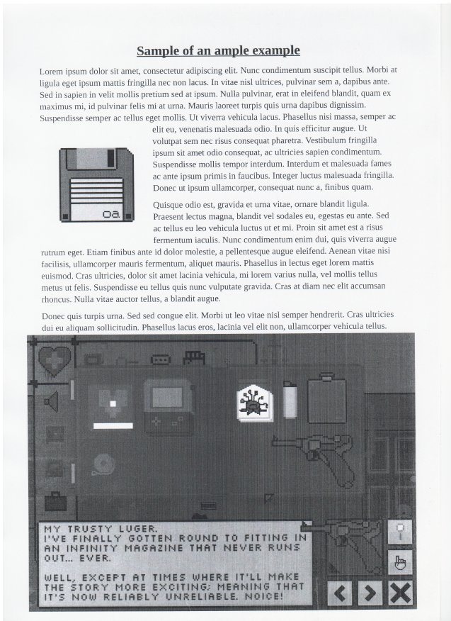
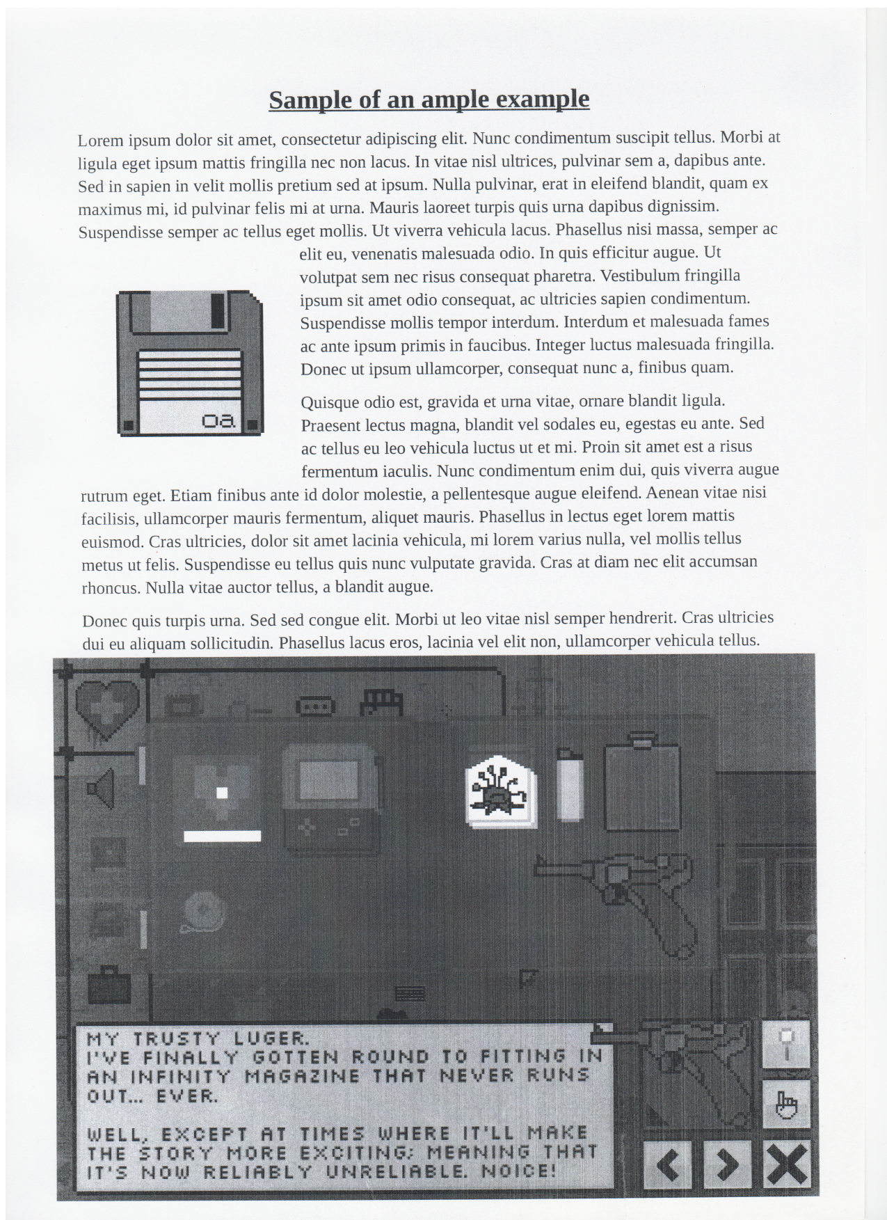
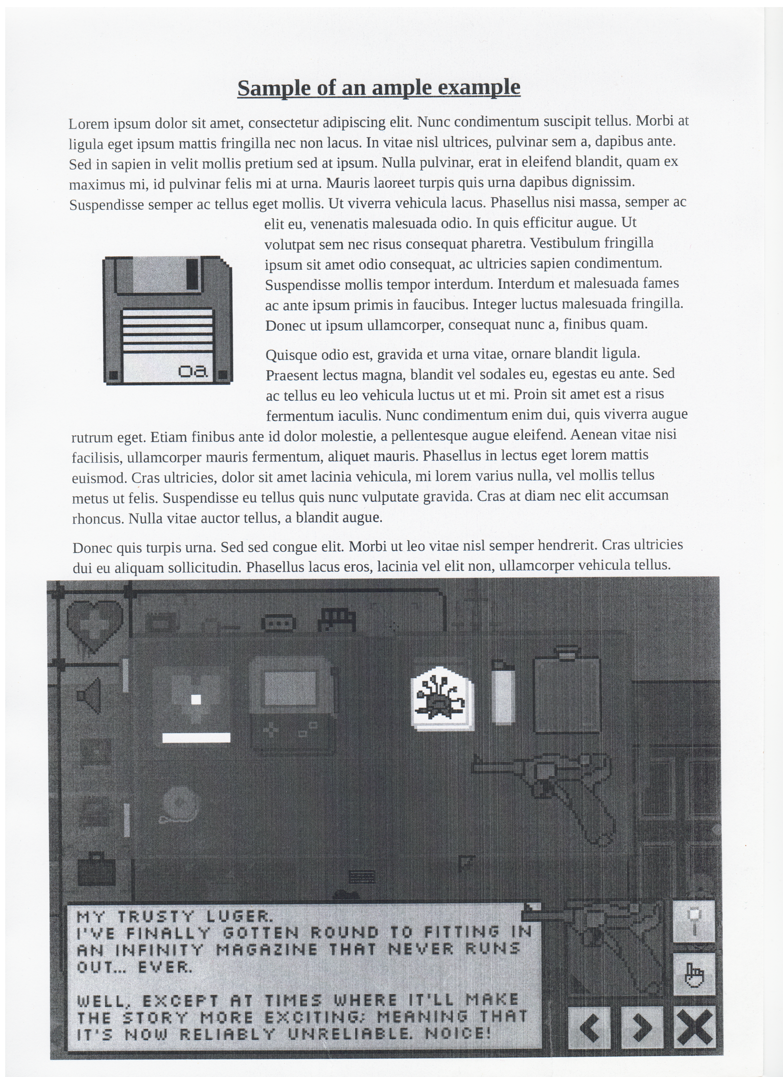
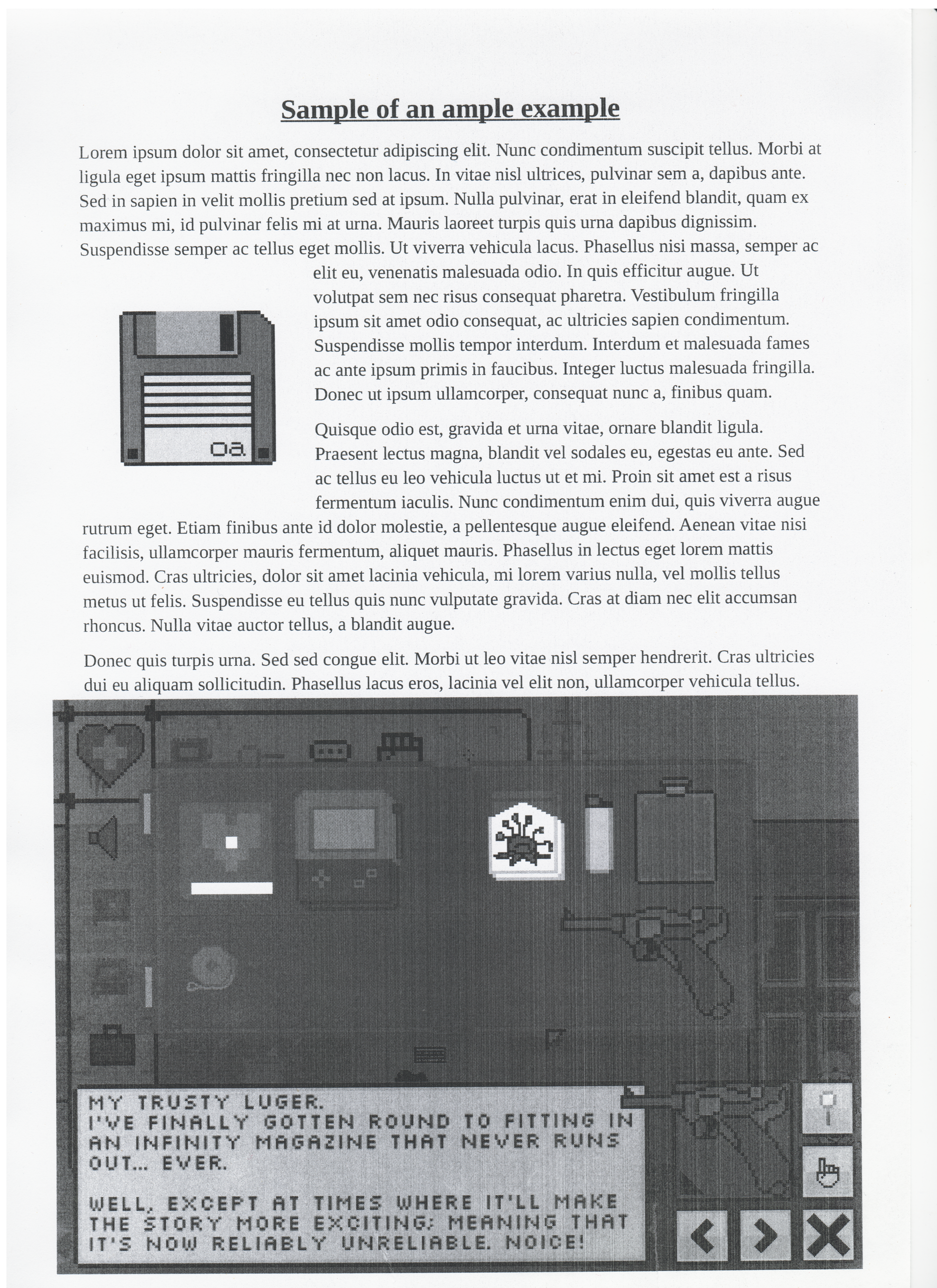